see if this helps more.
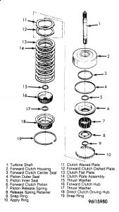
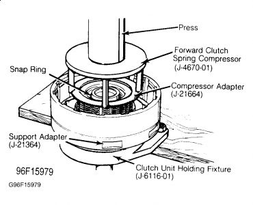
FORWARD CLUTCH Disassembly Place forward clutch assembly in Adapter and Holding Fixture (J-21364 and J-6116-01) with turbine shaft pointing down. Remove forward clutch housing-to-direct clutch hub snap ring and withdraw hub. Remove forward clutch hub and one thrust washer from each side of hub. See Fig. 20.Remove composition and steel clutch plates. Place forward clutch assembly in press with turbine shaft pointing down. Using Clutch Spring Compressor and Adapter (J-4670-01 and J-21664), compress spring retainer and remove snap ring. Remove tools. Lift out spring retainer and 16 clutch release springs. NOTE: Keep forward clutch release springs separate from direct clutch release springs. Fig. 20: Exploded View of Forward Clutch Assembly Courtesy of GENERAL MOTORS CORP. Remove forward clutch piston from housing. Remove inner and outer seals. Remove center piston seal from clutch housing. If turbine shaft or housing is damaged, place housing in press with shaft facing down. Using 3" driver, press turbine shaft out of forward clutch housing.
Inspection Inspect all components for wear or excessive damage. Ensure lubrication passages in housing, hub, and turbine shaft are clear. Check piston for cracks. Check turbine shaft and clutch housing for wear, scoring, or other damage. Ensure check ball in housing moves freely.
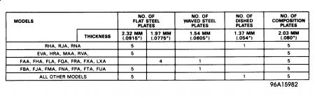
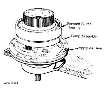
Reassembly If turbine shaft was removed, place forward clutch housing in press with flat side up. Align shorter splined end of turbine shaft with splines in forward clutch housing. Carefully press shaft into housing until shaft bottoms out. NOTE: Start shaft into housing, then back off press so shaft can straighten itself. Repeat until shaft is going in straight. Invert forward clutch housing on press with turbine shaft pointing down. Oil and install inner and outer seals on clutch piston with seal lips facing away from spring pockets. Oil and install center seal in clutch housing with seal lips facing upward. Place Inner Seal Protector (J-21362) over clutch hub. Place clutch piston into Installer (J-21409). Install assembly into housing, rotating piston clockwise slightly until seated. Install 16 clutch release springs into piston pockets. See Fig. 19.Place spring retainer over springs and compress springs with Compressor and Adapter (J-4670-01 and J-21664). Use care to avoid catching retainer in snap ring groove. Install snap ring. Remove tools and ensure all release springs are straight. Install forward clutch hub thrust washers. Ensure bronze washer is installed on side of hub facing forward clutch housing. Place forward clutch hub in clutch housing. Lubricate clutch plates with transmission fluid. Install clutch plates, starting with waved steel plate, then alternating composition and flat steel plates until all clutch plates are installed. See Fig. 22.Install direct clutch hub and retaining snap ring. Place forward clutch housing on oil pump delivery sleeve. Check operation of forward clutch by applying air through forward clutch passage.
ROAD TEST Connect tachometer to engine. Place selector lever in "Drive" range and accelerate vehicle from standstill at minimum throttle opening. The 1-2 and 2-3 up shifts should occur as vehicle reaches correct speed. As vehicle speed decreases, 3-2 and 2-1 downshifts and engine braking effect should be noticed. See SHIFT POINT SPECIFICATIONS.SHIFT POINT SPECIFICATIONS Application Speed (MPH)UpshiftMinimum1-2152-330Detent DownshiftMinimum3-268-732-128-32UpshiftMaximum1-244-482-377-83Stop vehicle and place selector lever in "2" (Intermediate) range. Accelerate from standstill. Upshift 1-2 should occur at all throttle openings (shift point will vary with throttle opening). The 2-3 upshift should occur. Stop vehicle and place selector lever in "1" (Low) range. Accelerate from standstill. No upshift should occur. With selector lever in Drive range and vehicle speed at 35 MPH, move selector lever to "2" (Intermediate) range. Transmission should downshift to 2nd gear. Increase in engine RPM and engine braking effect should be noticed. With selector lever in "2" (Intermediate) range and vehicle speed at 25-35 MPH (not over 40 MPH), move selector lever to "1" (Low) range. Throttle must be in closed position. Transmission should downshift to 1st gear. Increase in engine RPM and engine braking effect should be noticed. Stop vehicle and place selector lever in Reverse. Check for reverse operation.
CLUTCH & BAND APPLICATIONS Lever Position Elements In Use "D" Drive First Forward Clutch & Low Roller Clutch Second Forward Clutch, Intermediate Clutch & Intermediate Clutch Sprag Third Forward Clutch, Direct Clutch & Intermediate Clutch"2" Intermediate First Forward Clutch & Low Roller Clutch Second Forward Clutch, Front Band, Intermediate Clutch & Intermediate Clutch Sprag"1" Low First Forward Clutch, Low Roller Clutch & Rear Band Second Forward Clutch, Front Band, Intermediate Clutch & Intermediate Clutch Sprag Reverse Direct Clutch & Rear Band Neutral Or Park All Clutches And Bands Released Or Ineffective CONTROL PRESSURE CHECK
if you need more information let me know
Jan 23, 2010 at 10:47 AM