Hey Rjestes,
What happens is the diaphragm in the control valve goes bad and allows air to be injected into the exhaust system at all times which can make the car backfire.
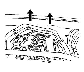
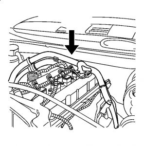
Here is where it is located.
Technical mubo-jumbo
Diagnostic Information for Finding a Restriction or Leak at Secondary Air Injection (SAI) System Inlet or Outlet Hoses - LL8 MIL/SES Light On, Repeat DTC P0411
TECHNICAL SERVICE BULLETIN
Reference Number(s): 06-06-04-016B, Date of Issue: April 20, 2007
Affected Model(s):2006-2007 Buick Rainier; 2006-2007 Chevrolet TrailBlazer; 2006-2007 GMC Envoy; 2006-2007 Saab 9-7X; with 4.2L Inline 6 Cylinder Engine (VIN S - RPO LL8)
SERVICE INFORMATION
IMPORTANT:The information provided in this Service Bulletin will aid ONLY in diagnosing a restriction or leak in the SAI system inlet or outlet hoses that cannot be detected by blowing shop air through them.
When diagnosing a Service Engine Soon (SES) light illuminated on the instrument cluster, technicians may find that the vehicle has previously been serviced for this same condition. Technicians may also find a DTC P0411, which may have led to previous SAI system component replacements.
An SES light illuminated due to P0411 - The diagnostic has detected an SAI system insufficient airflow due to a malfunctioning:
SAI system check valve
SAI system pump
SAI system relay and related control circuit
SAI system inlet or outlet hose restriction or leak
The information provided in this Service Bulletin will aid Only in diagnosing a restriction or leak in the SAI system inlet or outlet hoses that cannot be detected by blowing shop air through them. Be sure to follow the diagnostic information outline for DTC P0411 in SI. The following information provided in this bulletin will be used in conjunction with SI.
Procedure
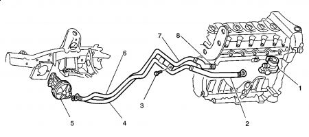
Fig. 1: SAI System Inlet And Outlet Hose Assembly
Courtesy of GENERAL MOTORS CORP.
SAI System Inlet and Outlet Hose Assembly
Air Shut-Off Valve
Inlet Hose to Air Cleaner
Retaining Bolt
Outlet Hose to Air Distribution Manifold
Air Pump
Inlet Hose to Air Distribution Manifold
Air Distribution Manifold and Retaining Bracket
Outlet Hose to Air Shut-Off Valve
IMPORTANT:Due to the complexity of these procedures, the following repair steps must be strictly adhered to in order to achieve the intended results. Any deviation or substitution may result in sub-standard repair resulting in repeat DTC P0411.
IMPORTANT:Refer to and copy all of the appropriate sections of SI repair procedures (Italicized) before attempting this repair.
Before using the following information outlined in this bulletin service procedure, Refer to DTC P0411 Diagnostic in SI. Make sure the diagnostic information for DTC P0411 in SI has been followed and led to a restriction or leak. The following information provided in this bulletin will further assist in diagnosing an SAI system inlet or outlet hose restriction or leak concern.
IMPORTANT:Additional Diagnostic Information on Secondary Air Injection (SAI) Systems can be found in GM TECH LINK Publication, February 2006 Volume 8, No 2.
When diagnosing the concern of a restriction or leak at the SAI system hoses, a normal reading of 20-25 kPa above BARO may be noted with the SAI system pump ON and the SAI system solenoid OFF. However, with the SAI system solenoid enabled, it may be noted that the SAI system pressure sensor parameter is not 8-12 kPa above the BARO reading, indicating an insufficient air flow condition has been detected due to a restriction or leak in the SAI system inlet or outlet hoses. The following diagnostic procedure determines if the SAI system is operating as designed:
SAI System Diagnostic Verification
Start and idle the engine for about 2 minutes to allow the SAI system diagnostic to run and complete.
The start-up coolant and ambient air temperatures have to be in the specified operating range.
SAI system pressure parameter should be BARO with a TECH 2(R).
Command the SAI system air pump relay ON. The SAI system air pump should operate. The TECH 2(R) parameter will indicate only that the SAI system air pump relay is commanded ON. The pump should dead-headed so the expected pressure would increase to a range of 18-25 kPa above BARO.
Command the SAI system air shut-off valve solenoid relay ON. The SAI system air pump should operate and the SAI system solenoid / check valve should open. The TECH 2(R) parameter will indicate that both SAI system relays are commanded ON. With the pump ON and the valve open, the expected pressure would increase to a range of 8-12 kPa above BARO.
After opening the valve in step 5, the pressure should decrease from the value read in step 4, but should not decrease all the way to the value read in step 3. The difference in readings between step 3 and step 5 should be greater than 8 kPa and in the range of 8-12 kPa. If the difference in readings between steps 3 and 5 is less than 8 kPa, this might be due to a restriction or leak in the SAI system but other possible root causes may exist. If this difference is less than 8 kPa, proceed to step number 7. If this difference is greater than 8 kPa, review the scan tool DTC information and refer to SI for further service procedures.
Temporarily remove the SAI system inlet hose from the SAI system air pump and enable the SAI system air shut-off valve solenoid with the Tech 2(R). If the SAI system pressure sensor parameter increases to 8-12 kPa above the BARO reading, the SAI system inlet hose is restricted and the SAI system inlet and outlet hose assembly should be replaced. If the SAI system pressure sensor parameter is not 8-12 kPa above the BARO reading, proceed to step number 8 of the SAI verification diagnostic procedure.
Temporarily substitute a 25.4 mm (1 in) O.D length of standard hose and route the hose from the SAI system air pump outlet to the SAI system air shut-off valve solenoid making sure that there are no kinks in the hose. Enable the SAI system air shut-off valve solenoid with the Tech 2(R). If the air pressure sensor parameter increases to 8-12 kPa above the BARO reading, the SAI system outlet hose is restricted and the SAI system Inlet and Outlet Hose Assembly should be replaced.
Install an SAI system Inlet and Outlet Hose Assembly, P/N 10373307, with Retaining Bolt, P/N 11519861 (M10 X 1.5 X 30), using the following procedures:
IMPORTANT:Refer to and copy all of the appropriate sections of SI repair procedures (Italicized) before attempting this repair.
Removal Procedure - SAI System Inlet and Outlet Hose Assembly
Relieve the fuel pressure. Refer to Fuel Pressure Relief Procedure in SI.
Disconnect the negative battery cable at the battery.
Raise the vehicle. Refer to Lifting and Jacking the vehicle in SI.
Disconnect inlet and outlet hoses from the SAI system air pump.
Remove the inlet and outlet hoses and retainer clip from the frame.
Lower the vehicle.
Disconnect the SAI system inlet hose from air cleaner.
Remove the air cleaner outlet resonator. Refer to Air Cleaner Outlet Resonator Replacement in SI.
Disconnect the SAI system outlet hose from the air shut-off valve.
Remove intake manifold. Refer to Intake Manifold Replacement in SI.
Remove the engine coolant temperature (ECT) harness connector.
Disconnect cylinder number 6 ignition coil engine harness connector.
Remove the retaining bolt from the ignition coil.
Remove the ignition coil from the engine.
Remove the retaining bolt (M10 X 1.5 X 30) and fir-tree fastener securing the SAI system Inlet and Outlet Hose Assembly to the rear of the engine cylinder head by using the following procedure:
Access the bolt by laying over the top of the engine.
Using a 15 mm standard length offset box end wrench, loosen the bolt.
Then use a short handle combination ratcheting box/open end 15 mm wrench to remove the bolt from the back of the cylinder head.
Once the bolt is removed from the engine cylinder head, the bolt will stay attached to the Air Distribution Manifold and Retaining Bracket. The fir-tree fastener will release itself from the back of the engine cylinder head by pushing back toward the cowl on the Air Distribution Manifold and Retaining Bracket.
Remove the SAI System Inlet and Outlet Hose Assembly by working the Air Distribution Manifold and Retaining Bracket in a back and forth upward motion past the back of the engine cylinder head via the cowl. Once the complete assembly has past the back of the cam cover, continue to work the SAI System Inlet and Outlet Hose Assembly out of the engine compartment. Refer to the illustration above.
Installation Procedure - SAI System Inlet and Outlet Hose Assembly
Install the retaining bolt, P/N 11519861, (M10 X 1.5 X 25) to the Air Distribution Manifold and Retaining Bracket. Then, apply Medium-Strength Threadlocker (Blue), U.S. P/N 12345382 (Canadian Part Number 10953489), or equivalent, to the retaining bolt.
Install the SAI System Inlet and Outlet Hose Assembly, P/N 10373307, by working the Air Distribution Manifold and Retaining Bracket with the hoses attached in a back and forth downward motion past the back of the engine cylinder head via the cowl. Once the complete assembly has past the back of the cam cover, continue to work the SAI System Inlet and Outlet Hose Assembly into the engine compartment and into place. Once in place, by feel locate by hand and start the retaining bolt into the back of the cylinder head, and at the same time locate and install the fir-tree fastener and push into place. Tighten the bolt until the clamp load of the bolt secures the Air Distribution Manifold and Retaining Bracket to the back of the engine cylinder head. Refer to the illustration above.
Install cylinder number 6 ignition coil.
NOTE:Use the correct fastener in the correct location. Replacement fasteners must be the correct part number for that application. Fasteners requiring replacement or fasteners requiring the use of thread locking compound or sealant are identified in the service procedure. Do not use paints, lubricants, or corrosion inhibitors on fasteners or fastener joint surfaces unless specified. These coatings affect fastener torque and joint clamping force and may damage the fastener. Use the correct tightening sequence and specifications when installing fasteners in order to avoid damage to parts and systems.
Please let us know happens so it will help others.
Best, Ken
Dec 4, 2016 at 6:49 PM

