REMOVAL PROCEDURE
1. Remove the brake modulator assembly.
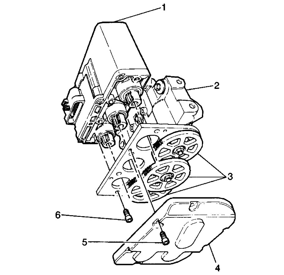
2. Remove the Torx head screws (5) attaching the gear cover (4).
3. Remove the gear cover (4).
4. Remove the four Torx head screws (6) attaching the motor pack (1) to the brake modulator (2).
5. Remove the motor pack (1) from the brake modulator (2).
6. Remove the Torx head screws that retain the proportioning valve.
7. Remove the proportioning valve.
INSTALLATION PROCEDURE
IMPORTANT: When replacing the ABS brake modulator, install the three gears in the same location on the replacement brake modulator. Refer to "Brake Modulator Gear Replacement".
No repair of the ABS brake modulator is authorized. Replace the ABS brake modulator as an assembly.
1. Install the proportioning valve to the hydraulic modulator.
2. Install the Torx head screws that retain the proportioning valve to the hydraulic modulator.
- Tighten the Torx head screws to 12 Nm (106 in. Lbs.).
IMPORTANT: A new gasket MUST be used when installing the Proportioning Valve.
3. With the ABS brake modulator positioned upside down, and the gears facing you, rotate each ABS brake modulator gear clockwise until movement stops.
The procedure causes the following conditions:
- The pistons are positioned very close to the top of the modulator bore.
- The brake bleeding procedure is simplified.
4. Install the ABS brake motor pack (1) onto the brake modulator assembly (2).
5. Install the four Torx head screws (6) that retain the motor pack (1) to the brake modulator (2).
- Tighten the four Torx head screws to 5 Nm (44 in. Lbs.).
6. Install the gear cover (4) to the brake modulator assembly (2).
7. Install the Torx head screws (5) that retain the gear cover (4).
- Tighten the Torx head screws to 4 Nm (36 in. Lbs.).
8. Install the brake modulator assembly.
9. Perform the Diagnostic System Check.
See diagram below
Image (Click to make bigger)
Monday, March 29th, 2021 AT 2:41 PM