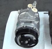
3.1 or 3.8?
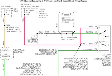
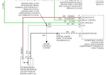
A/C CLUTCH CIRCUIT DIAGNOSIS To help save diagnostic time, ALWAYS check for blown fuses or fusible links before proceeding with any testing. If fuses are blown, locate and repair short circuit before replacing fuses. Ensure all related relay and wire harness connections are clean and tight. Repair as necessary. See WIRING DIAGRAMS . 3.1L Description When A/C is selected through A/C control panel, a 12-volt signal is supplied to A/C request input terminal of PCM. A/C clutch relay is controlled through PCM which also monitors A/C refrigerant pressure. If A/C refrigerant pressure and engine operating conditions are within a specific calibrated acceptable range, PCM will enable A/C clutch relay. This is accomplished by providing a ground path for A/C clutch relay coil with PCM. When A/C clutch relay is enabled, battery voltage is supplied to compressor clutch coil. PCM will enable compressor clutch whenever engine is running and A/C has been requested, unless: � � � Throttle angle is greater than 90 percent. � � � A/C head pressure is greater than 414 psi (29.1 kg/cm 2 ). � � � A/C head pressure is less than 35 psi (2.5 kg/cm 2 ). � � � Ignition voltage is less than 10.5 volts. � � � Engine speed is greater than 4500 RPM for 5 seconds. � � � Engine coolant temperature is greater than 257 °F (125 °C). � � � Intake air temperature is less than 41 °F (5 °C). Diagnosis 1. If On-Board Diagnostic (OBD) System Check has not been performed, see OBD SYSTEM CHECK in TESTS W/CODES article in ENGINE PERFORMANCE. If OBD SYSTEM CHECK has been performed, go to next step. 2. Install scan tool. Check if any DTCs are set. If any DTCs are set, perform diagnosis for DTCs first. See TESTS W/CODES article in ENGINE PERFORMANCE. If no DTCs are set, go to next step. WARNING: Vehicles may be equipped with a PCM using an Electronically Erasable Programmable Read Only Memory (EEPROM). When replacing PCM, the new PCM must be programmed. NOTE: Body Function Controller (BFC) may also be known as Body Control Module (BCM). 3. Ensure ambient air temperature is greater than 41 °F (5 °C), A/C pressure is greater than 35 psi (2.5 kg/cm 2 ) (.40 volt on scan tool), and coolant temperature is less than 250 °F (121 °C). Turn A/C off. Turn ignition on, engine off. Listen for engagement of compressor clutch. If compressor clutch engages, go to step 18). If compressor clutch does not engage, go to next step. 4. With engine running at idle, select DEFROST or MAX mode. Observe compressor clutch. If compressor clutch is engaged, problem may be intermittent. If compressor clutch is not engaged, go to next step. 5. With DEFROST or MAX mode selected, monitor A/C REQUEST display on scan tool engine data list. If A/C REQUEST displays YES, go to step 9). If A/C REQUEST does not display YES, go to next step. 6. Turn ignition off. Disconnect PCM harness connectors. Turn ignition on. With DEFROST or MAX mode selected, use a DVOM and measure voltage on A/C request circuit at PCM harness connector. If battery voltage is present, go to step 8). If battery voltage is not present, go to next step. 7. Check A/C request circuit for an open, short to ground or poor connection at A/C control head/programmer. Repair as necessary. Go to step 29). If no problem is found, diagnose A/C controls. See A/C-HEATER SYSTEM article. 8. Check A/C request circuit for a poor connection at PCM. Repair as necessary. Go to step 29). If no problem is found, go to step 27). 9. Observe A/C refrigerant pressure display on scan tool. If pressure is 36-440 psi (2.5-30.9 kg/cm 2 ), go to step 12). If pressure is not as specified, go to next step. 10. Install A/C manifold gauge set. Observe high-side refrigerant pressure. If pressure is 36-440 psi (2.5-30 kg/cm 2 ), go to next step. If pressure is not as specified, charge A/C system using approved A/C refrigerant recovery/recycling equipment. Go to step 29). 11. Turn ignition off. Disconnect A/C pressure sensor. Turn ignition on. View A/C HIGH-SIDE display on scan tool engine data list. If scan tool displays A/C high-side pressure as 0 psi (0 kg/cm 2 ), go to step 28). If scan tool does not display A/C high-side pressure as specified, go to step 27). 12. Disconnect A/C clutch relay. Using a test light connected to ground, probe both ignition feed circuit terminals (Pink wires) at A/C clutch relay harness connector. If test light illuminates at both terminals, go to next step. If test light does not illuminate at both terminals, go to step 23). 13. Connect a fused jumper wire between one ignition feed circuit (Pink wire) and compressor clutch battery feed circuit (Dark Green wire) at A/C clutch relay harness connector. If compressor clutch engages, go to next step. If compressor clutch does not engage, leave jumper wire in place and go to step 15). 14. Check for poor connections at A/C clutch relay. Repair as necessary. Go to step 29). If no problem is found, go to step 24). 15. Disconnect compressor clutch harness connector. Connect a test light between compressor clutch battery feed circuit (Dark Green wire) and compressor clutch ground circuit (Black wire). If test light illuminates, go to next step. If test light does not illuminate, go to step 17). 16. Check for poor connections at compressor clutch. Repair as necessary. Go to step 29). If no problem is found, go to step 25). 17. Check for an open or short to ground in compressor clutch battery feed circuit (Dark Green wire). Repair as necessary. Go to step 29). If no problem is found, go to step 26). 18. Turn ignition on, A/C off. Observe A/C REQUEST display on scan tool. If A/C REQUEST displays YES, go to next step. If A/C REQUEST does not display YES, go to step 21).
19. Turn ignition off. Disconnect PCM harness connectors. Turn ignition on, A/C off. Using a DVOM, measure voltage between ground and A/C request circuit at PCM harness connector. If reading is near battery voltage, go to next step. If reading is not as specified, go to step 27). 20. Turn ignition off. Disconnect Body Function Controller (BFC). Turn ignition on. Check A/C request circuit for a short to power. Repair as necessary. Go to step 29). If no problem is found, diagnose A/C controls. See A/C-HEATER SYSTEM article. 21. Disconnect A/C clutch relay. Start engine and observe compressor clutch. If compressor clutch is engaged, go to next step. If compressor clutch is not engaged, go to step 24). 22. Locate and repair short to power in compressor clutch battery feed circuit (Dark Green wire). Go to step 29). 23. Repair open or short to ground in A/C clutch relay ignition feed circuit (Pink wire). Go to step 29). 24. Replace A/C clutch relay. Go to step 29). 25. Replace compressor clutch coil. Go to step 29). 26. Locate and repair open in compressor clutch ground circuit (Black wire). Go to step 29). 27. Replace PCM. Go to step 29). 28. Replace A/C pressure sensor. Go to next step. 29. Ensure ambient air temperature is greater than 41 °F (5 °C), A/C pressure is greater than 96 °F (36 ° C), and coolant temperature is less than 250 °F (121 °C). Start engine and let idle. Turn A/C on. Listen for engagement of compressor clutch. If compressor clutch engages, system is okay. If compressor clutch does not engage, go to step 3). 3.8L Description When A/C mode is selected, a 12-volt signal is supplied to the A/C request input terminal of PCM. A/C clutch relay is controlled through PCM which also monitors A/C refrigerant pressure. If A/C refrigerant pressure and engine operating conditions are within a specific calibrated acceptable range, PCM will enable A/C clutch relay. This is done by providing a ground path for A/C clutch relay coil in PCM. When A/C clutch relay is enabled, battery voltage is supplied to compressor clutch coil. PCM will enable compressor clutch whenever engine is running and A/C has been requested, unless: � � � Throttle angle is greater than 96 percent. � � � A/C head pressure is greater than 440 psi (30.9 kg/cm 2 ). � � � A/C head pressure is less than 32 psi (2.2 kg/cm 2 ). � � � Ignition voltage is less than 10 volts. � � � Engine speed is greater than 4400 RPM for any length of time. � � � Engine coolant temperature is greater than 255 °F (124 °C). � � � Intake air temperature is less than 41 °F (5 °C).
1. If On-Board Diagnostic (OBD) System Check has not been performed, see OBD SYSTEM CHECK in TESTS W/CODES article in ENGINE PERFORMANCE. If OBD SYSTEM CHECK has been performed, go to next step. 2. Install scan tool. Check if any DTCs are set. If any DTCs are set, perform diagnosis for DTCs first. See TESTS W/CODES article in ENGINE PERFORMANCE. If no DTCs are set, go to next step. 3. Ensure ambient air temperature is greater than 41 °F (5 °C), A/C pressure is greater than 32 psi (2.2 kg/cm 2 ), and coolant temperature is less than 250 °F (121 °C). Turn A/C off. Turn ignition on, engine off. Listen for engagement of compressor clutch. If compressor clutch engages, go to step 24). If compressor clutch does not engage, go to next step. 4. With engine running at idle, select A/C mode on A/C control panel. Observe compressor clutch. If compressor clutch is engaged, problem may be intermittent. See DIAGNOSTIC AIDS. If compressor clutch is not engaged, go to next step. 5. With A/C mode selected, monitor A/C REQUEST display on scan tool engine data list. If A/C REQUEST displays YES, go to step 9). If A/C REQUEST does not display YES, go to next step. 6. Turn ignition off. Disconnect PCM harness connectors. Turn ignition on. With A/C mode selected, use a DVOM and measure voltage on A/C request circuit (Dark Green/White wire) at PCM harness connector. If battery voltage is present, go to step 8). If battery voltage is not present, go to next step. 7. Check A/C request circuit (Dark Green/White wire) for an open, short to ground or poor connection at A/C control head/programmer. Repair as necessary. Go to step 42). If no problem is found, diagnose A/C controls. See A/C-HEATER SYSTEM article. 8. Check A/C request circuit (Dark Green/White wire) for a poor connection at PCM. Repair as necessary. Go to step 42). If no problem is found, go to step 40). 9. Observe A/C refrigerant pressure display on scan tool. If pressure is 32-440 psi (2.2-30.9 kg/cm 2 ), go to step 12). If pressure is not as specified, go to next step. 10. Install A/C manifold gauge set. Observe high-side refrigerant pressure. If pressure is 32-440 psi (2.2-30 kg/cm 2 ), go to next step. If pressure is not as specified, charge A/C system using approved A/C refrigerant recovery/recycling equipment. 11. Turn ignition off. Disconnect A/C pressure sensor. Turn ignition on. View A/C HIGH-SIDE display on scan tool engine data list. If scan tool displays A/C HIGH-SIDE as 0 psi (0 kg/cm 2 ), go to step 41). If scan tool does not display A/C HIGH-SIDE as specified, go to step 40). 12. Check A/C clutch relay fuse (10-amp), located in underhood fuse/relay box. If fuse is blown, go to next. If fuse is okay, go to step 17). 13. Turn ignition off. Remove A/C clutch fuse and A/C clutch relay. Using a test light connected to battery voltage, probe both ignition feed circuits at A/C clutch relay connector. If test light illuminates, go to step 31). If test light does not illuminate, go to next step. 14. Leave A/C clutch relay disconnected. Disconnect compressor clutch harness connector. Using a test light connected to battery voltage, probe compressor clutch battery feed circuit (Dark Green wire) at A/C clutch relay connector. If test light illuminates, go to step 32). If test light does not illuminate, go to next step. 15. Check for an open compressor clutch diode. Repair as necessary. Go to step 42). If no problem is found, go to next step. 16. Turn ignition off. Reconnect A/C clutch relay. Disconnect PCM harness connectors. Turn ignition on. Using a DVOM set to 10-amp scale, measure current draw between ground and A/C clutch relay control circuit (Dark Green/White wire) at PCM harness connector for at least 2 minutes. If
current draw is .5-1.5 amps, go to step 38). If current draw is not as specified, go to step 39). 17. Turn ignition off. Remove A/C clutch relay. Turn ignition on. Using a test light connected to ground, probe A/C clutch relay ignition feed circuits in A/C clutch relay connector. If test light illuminates, go to next step. If test light does not illuminate, go to step 33). 18. Leave A/C clutch relay disconnected. Connect a 10-amp fused jumper wire between A/C clutch relay ignition feed circuit and compressor clutch battery feed circuit in A/C clutch relay connector. If compressor clutch engages, go to step 21). If compressor clutch does not engage, go to next step. 19. Leave jumper wire connected. Disconnect compressor clutch harness connector. Using a test light connected to ground, probe compressor clutch battery feed circuit (Dark Green wire) at compressor clutch connector. If test light illuminates, go to next step. If test light does not illuminate, go to step 34). 20. Using a test light connected to battery voltage, probe compressor clutch ground circuit (Black wire) at compressor clutch harness connector. If test light illuminates, go to step 38). If test light does not illuminate, go to step 35). 21. Leave A/C clutch relay disconnected. Connect a test light between A/C clutch relay ignition feed and control circuits at A/C clutch relay connector. Using scan tool in OUTPUT FUNCTIONS mode, cycle A/C clutch relay on and off. If test light flashes on and off, go to next step. If test light does not flash on and off, go to step 23). 22. Check A/C relay for poor connections. Repair as necessary. Go to step 42). If no problem is found, go to step 39). 23. Check for an open in A/C clutch relay control circuit (Dark Green/White wire) or poor terminal connection at PCM. Repair as necessary. Go to step 42). If no problem is found, go to step 40). 24. Turn ignition on, A/C off. Observe A/C REQUEST display on scan tool. If A/C REQUEST displays YES, go to next step. If A/C REQUEST does not display YES, go to step 27). 25. Turn ignition off. Disconnect PCM harness connectors. Turn ignition on, A/C off. Using a DVOM, measure voltage between ground and A/C request circuit (Dark Green/White wire) at PCM harness connector. If reading is near battery voltage, go to next step. If reading is not as specified, go to step 27). 26. Turn ignition off. Disconnect A/C control head harness connector. Turn ignition on. Using a DVOM, check A/C request circuit (Dark Green/White wire) for a short to power. Repair as necessary. Go to step 42). If no problem is found, diagnose A/C controls. See procedures in A/C- HEATER SYSTEM article. 27. Leave A/C off. Disconnect A/C clutch relay. Start engine and observe compressor clutch. If compressor clutch is engaged, go to next step. If compressor clutch is not engaged, go to step 29). 28. Turn ignition off. Disconnect compressor clutch harness connector. Start engine. If compressor clutch engages, go to step 38). If compressor clutch does not engage, go to step 36). 29. Turn ignition off. Leave A/C clutch relay disconnected with A/C off. Using a test light connected to battery voltage, probe A/C clutch relay control circuit (Dark Green/White wire) at A/C clutch relay connector. Turn ignition on. If test light illuminates, leave test light connected and go to next step. If test light does not illuminate, go to step 39). 30. Disconnect PCM harness connectors. Turn ignition on. Probe A/C clutch relay control circuit (Dark Green/White wire) in A/C clutch relay connector. If test light illuminates, go to step 37). If test light does not illuminate, go to step 40). 31. Locate and repair short to ground in ignition feed circuits to A/C clutch relay. Go to step 42). 32. Locate and repair short to ground in compressor clutch battery feed circuit (Dark Green wire)
and/or shorted compressor clutch diode. Go to step 42). 33. Locate and repair open in ignition feed circuits to A/C clutch relay. Go to step 42). 34. Locate and repair open in compressor clutch battery feed circuit (Dark Green wire). Go to step 42). 35. Locate and repair open in compressor clutch ground circuit (Black wire). Go to step 42). 36. Locate and repair short to power in compressor clutch battery feed circuit (Dark Green wire). Go to step 42). 37. Locate and repair short to ground in A/C clutch relay control circuit (Dark Green/White wire). Go to step 42). 38. Replace compressor clutch coil assembly. Go to step 42). 39. Replace A/C clutch relay. Go to step 42). 40. Replace PCM. Go to step 42). 41. Replace A/C pressure sensor. Go to step 42). 42. Ensure ambient air temperature is greater than 41 °F (5 °C), A/C pressure is greater than 32 psi (2.2 kg/cm 2 ), and coolant temperature is less than 250 °F (121 °C). Start engine and let idle. Turn A/C on. Listen for engagement of compressor clutch. If compressor clutch engages, system is okay. If compressor clutch does not engage, go to step 3). Diagnostic Aids Check for poor harness connections at PCM. Inspect for corrosion, backed-out terminal pins and broken wires inside insulation. Check for damaged wire harness. If harness and connections are okay, disconnect PCM harness connectors. Connect a DVOM between ground and A/C clutch relay control circuit at PCM harness connector. Turn ignition on. Observe DVOM while wiggling harness and connectors. A change in voltage indicates location of fault. A/C refrigerant pressure less than 32 psi (2.2 kg/cm 2 ), or greater than 440 psi (30.9 kg/cm 2 ) will cause PCM to disable compressor clutch. With engine running and A/C on, use scan tool to monitor A/C high- side system pressure for 2 minutes. If pressure goes out of range, diagnose A/C-heater system. See A/C- HEATER SYSTEM article.
Saturday, February 14th, 2009 AT 4:23 AM