Check the blower motor resistor, usually the problem.
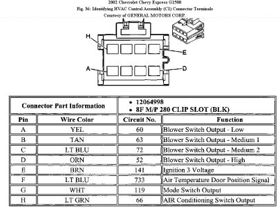
TEST E: BLOWER MOTOR INOPERATIVE 1. If review of system operation has been performed, go to next step. If review of system operation has not been performed, see DESCRIPTION and OPERATION . 2. Turn ignition on. Place mode switch in any position except off. Place blower switch in each speed position. If blower motor is inoperative in all speed positions, go to next step. If blower motor operates in any speed position, go to TEST F: BLOWER MOTOR MALFUNCTION . 3. Turn ignition off. Disconnect blower motor harness connector. Turn ignition on. Using a test light connected to ground, probe voltage supply terminal (Purple wire) at blower motor connector. DO NOT probe blower motor ground circuit (Black wire) terminal. Place blower switch in minimum speed position. If test light illuminates, go to next step. If test light does not illuminate, go to step 5 . 4. Connect a test light between voltage supply terminal (Purple wire) and ground circuit terminal (Black wire) at blower motor connector. Place blower switch in minimum speed position. If test light illuminates, go to step 11 . If test light does not illuminate, go to step 9 . 5. Turn ignition off. Disconnect harness connector from blower motor resistor. Turn ignition on. Place blower switch in minimum speed position. Using a test light connected to ground, probe blower low speed control circuit (Yellow wire) at terminal "E" at resistor connector. See WIRING DIAGRAMS . If test light illuminates, go to step 10 . If test light does not illuminate, go to next step. 6. Check all blower motor speed circuits for a short to ground. See WIRING DIAGRAMS . If a short to ground was found, repair as necessary and go to step 17 . If a short to ground was not found, go to next step. 7. Turn ignition off. Disconnect 8-pin C1 harness connector from main HVAC control assembly. Turn ignition on. Using a test light connected to ground, probe ignition 3 voltage circuit (Brown wire) at terminal "E" of HVAC control C1 connector. See Fig. 6 . If test light illuminates, go to next step. If test light does not illuminate, go to step 13 . Fig. 6: Identifying HVAC Control C1 Harness Connector Terminals Courtesy of GENERAL MOTORS CORP. 8. Check voltage supply circuit (White wire) to blower switch for an open or high resistance. See WIRING DIAGRAMS . If an open or high resistance was found, repair as necessary and go to step 17 . If an open or high resistance was not found, go to step 12 . 9. Check ground circuit (Black wire) to blower motor resistor for an open or high resistance. See WIRING DIAGRAMS . If an open or high resistance was found, repair as necessary and go to step 17 . If an open or high resistance was not found, go to next step. 10. Check harness connector at blower motor resistor for a poor connection. If a poor connection was found, repair as necessary and go to step 17 . If a poor connection was not found, go to step 16 . NOTE: For circuit reference, see CONNECTOR IDENTIFICATION and/or WIRING DIAGRAMS . NOTE: Definition: The blower motor is inoperative in all speed positions. 11. Check harness connector at blower motor for a poor connection. If a poor connection was found, repair as necessary and go to step 17 . If a poor connection was not found, go to step 15 . 12. Check harness connector at main HVAC control assembly for a poor connection. If a poor connection was found, repair as necessary and go to step 17 . If a poor connection was not found, go to step 17 . 13. Repair the short to ground or open condition in ignition 3 voltage supply circuit (Brown wire) to main HVAC control assembly. See WIRING DIAGRAMS . If repair is complete, go to step 17 . 14. Replace blower motor resistor. See Fig. 18 . After repairs are complete, go to step 17 . 15. Replace blower motor. See BLOWER MOTORS under REMOVAL & INSTALLATION. After repairs are complete, go to step 17 . 16. Replace main HVAC control assembly. See MAIN HVAC CONTROL ASSEMBLY under REMOVAL & INSTALLATION. If replacement is complete, go to next step. 17. Operate system to verify repair. If the condition was corrected, system is okay. If the condition was not corrected, go to step 2 .
Jul 11, 2009 at 9:23 AM