1993 Chevy Cavalier INTERIOR ETHONAL ODER-ExCESSIVE TANK PR

Tiny
SAVED
  • MEMBER
  • 1993 CHEVROLET CAVALIER
Smells problem
1993 Chevy Cavalier 4 cyl Front Wheel Drive Automatic

Charcoal canister vacuum line to purge vale
has fuel in it?
Removed the Canister line that I believe returns to tank:
it too has presence of fuel?

Purge vale: using vacuum tool. Will hold a vacum.
with no vacuum present: DOSE NOT allow flow
with vacuum applied: allows thru-flow

this was preceded by. Presence of ethanol smell in passenger compartment? With engine off and while removing fuel tank gas cap: I WAS SHOCKED how much pressure had built up in the tank? IT took some seconds of tine for it to relieve itself?

Earlier in the day. I had removed the charcoal canister
to blow through w/ low pressure to check flow?
[REASON for this has been a rough IDLE in drive.
drivability enhanced by shifting into neutral at stop lights (the idel roughness will continue to worsen if left in drive-)]

observed vacum hose at port to purge vale slightly collapsed. Figuring incorrect hose material IE non-gas approved.

SO the main matter is this tank pressure and fuel in the line presence?

thanks
Thursday, August 19th, 2010 AT 8:47 AM

7 Replies

Tiny
MERLIN2021
  • MECHANIC
  • 17,250 POSTS
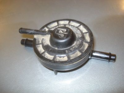
If the canister has fuel in it too it needs to be replaced, next read the codes.
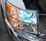
Cross these two terminals as shown, then turn the key on. Count the flashes, a 22 will flash as 2 flashes then a short pause, then 2 flashes, if more than one code is stored, the pause will be longer. The codes will display three times and end with 12. Write them down and post here. This connector is right under the middle of the dash...
RETRIEVING CODES (WITHOUT SCAN TOOL)
NOTE: The Assembly Line Data Link (ALDL) may also be referred to as the Data
Link Connector (DLC).
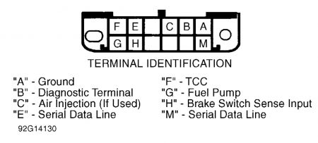
With key on and engine off, locate Assembly Line Data Link (ALDL) connector under dash, on
driver's side of vehicle. Connect a jumper wire between ALDL terminal "B" (test terminal) and
terminal "A" (ground terminal). See Fig. 2. This places control module in diagnostic mode.
1.
NOTE: Connecting terminals "A" and "B" of ALDL connector with engine
running will cause fuel injected vehicles to enter field service
mode. The MIL (SERVICE ENGINE SOON) light will not flash codes
if this is done.
Fig. 2:
In this mode, control module will display DTC 12 by flashing MIL (SERVICE ENGINE SOON)
light. DTC 12 is identified by MIL (SERVICE ENGINE SOON) light flashing once, followed
by a short pause, then 2 flashes in quick succession.
2.
Each DTC will be repeated 3 times. DTC 21 is identified by 2 flashes, a short pause followed by
one flash; DTC 53 is identified by 5 flashes, a short pause followed by 3 flashes. DTC's are
separated by slightly longer pauses.
3.
DTC's are displayed in numerical order. Each code is displayed 3 times. DTC's will continue to
repeat as long as ALDL test terminal is grounded. If DTC's are not flashed, or MIL (SERVICE
ENGINE SOON) light does not glow, self-diagnostics will not work. See CHART A-1 under
DIAGNOSTIC CHARTS.
5.
NOTE: DTC's will be recorded at various operating times. Some codes require
operation of sensor or switch for 5 seconds; others may require
operation for 5 minutes or longer at normal operating temperature, road
speed and load. Therefore, some codes may not set in a service bay
operational mode, but may require road testing vehicle in order to
duplicate condition under which code will set.


https://www.2carpros.com/forum/automotive_pictures/62217_GM_OBDI_2.jpg

Was this
answer
helpful?
Yes
No
Friday, August 20th, 2010 AT 8:42 AM
Tiny
SAVED
  • MEMBER
  • 4 POSTS
By way of review...on the charcoal canister exist 3-ports:
1-to atmosphere
1-to attachment at purge vale &
1-to a return line (cannot see where it goes) but must go to tank.

Merlin said (paraphrasing) if canister has fuel in it: REPLACE

No fuel is present in canister; however...
in the line from the canister to the purge valve I cleared (gently blew-out fuel liquid); and when gentle air was applied to what I'll call 'to the tank line' you could here/see slight evidence of fuel too? I did not attempt to apply more air flow not knowing where this line was connected at the fuel tank? IS THERE some device that could be damaged (like a one-way valve or another vacuum device???) when air would be used to 'clean out' any liquid fuel?

REF purge valve...I put the vacuum to the port...while removed from the engine...
it appears to function properly (with vacuum applied one can move air through the valve & with-out vacuum there is no flow through). GOOD PURGE VALVE?

PURGE VALVE TO ENGINE CONNECTIONS:
vacuum port at engine is sucking BUT
the larger port shows no evidence of suction: is this correct? IF not why?

COMPUTER CODE REF in your response...
no codes stored: only the 12 code.

what do you say?


https://www.2carpros.com/forum/automotive_pictures/563219_CANISTER_PURGE_VALVE_002_1.jpg

Was this
answer
helpful?
Yes
No
Friday, August 20th, 2010 AT 10:07 AM
Tiny
MERLIN2021
  • MECHANIC
  • 17,250 POSTS
Canister Purge Solenoid (Normally Closed) 1. Disconnect canister purge solenoid harness connector and vacuum hose. Apply 10 in. Hg to ported intake manifold vacuum side of solenoid valve. If vacuum holds, go to next step. If vacuum does not hold, replace canister purge solenoid. 2. Using a 12-volt power source, energize canister purge solenoid. Vacuum should release. If vacuum does not release, replace canister purge solenoid. Solenoid resistance should be at least 20 ohms. Fuel Tank Pressure Control Valve Apply approximately 15 in. Hg to fuel tank pressure control valve. The diaphragm should hold vacuum for at least 20 seconds. If fuel tank pressure control valve does not hold vacuum, replace tank pressure control valve. POSITIVE CRANKCASE VENTILATION (PCV) Required Service The PCV system may require service for obstructions if any of the following conditions exist: Ã Â Â Rough idle. Ã Â Â Stalling or slow idle speed. Ã Â Â Oil leaks. Ã Â Â Oil in air cleaner. Ã Â Â Sludge in engine. A leaking PCV valve or hose could cause: Ã Â Â Rough idle. Ã Â Â Stalling. Ã Â Â High idle speed. If engine idles roughly, check for clogged PCV valve or plugged or broken hoses BEFORE adjusting idle. Check PCV valve application to ensure the correct valve is fitted. Replace PCV valve if required. Checking PCV Valve Function 1. Remove PCV valve from rocker cover. Run engine at idle. Place thumb over open end of valve to check for vacuum. If there is no vacuum at valve, check for obstruction in manifold port, hoses or PCV valve. Repair or replace as necessary. 2. Turn engine off. Remove PCV valve. Shake valve and listen for rattle of check valve inside. If a clear rattle is not heard, replace PCV valve. 3. Visually inspect valve for varnish or deposits which may make PCV valve operation sticky or restricted, or cause incomplete seating of valve. Replace if necessary. 4. An engine must be sealed for the PCV system to function as designed. If leakage, sludging or dilution of oil is noted and the PCV system is functioning properly, check engine for cause and repair as required to ensure PCV system will continue to function properly. 5. An engine operating without any crankcase ventilation can be damaged, so it is important to replace PCV valve and air cleaner breather (if equipped) at regular intervals (at least every 30,000 miles). Check all hoses and clamps for failure or deterioration. Crankcase Ventilation Heater (2.3L) 1. Turn ignition on. Connect test light between crankcase ventilation heater assembly connector. See Fig. 6 . Test light should illuminate. If test light did not illuminate, check 25-amp A/C- heater fuse or for an open in circuit. If test light illuminated, go to next step. 2. Turn ignition off. Disconnect harness connector from crankcase ventilation heater assembly. Using an ohmmeter, measure crankcase ventilation heater resistance at room temperature. Resistance should be 2-6 ohms. If resistance is as specified, go to next step. If resistance is not as specified, replace crankcase ventilation heater assembly. 3. Reconnect crankcase ventilation heater assembly harness connector, but DO NOT install assembly on engine. Turn ignition on for one minute. Heating element should be warm to the touch. If heating element does not warm up, inspect wiring harness and harness connector for proper connection or replace defective crankcase ventilation heater assembly. Fuel Pressure Regulator (PFI) 1. Install fuel pressure gauge to fuel rail fuel pressure test fitting. Remove vacuum hose from fuel pressure regulator. Turn ignition on and note fuel pressure on gauge. 2. Start engine. Check for manifold vacuum at pressure regulator vacuum hose. If vacuum is not present, repair as necessary. Reconnect vacuum hose to pressure regulator and note fuel pressure on gauge. Compare first and second reading. 3. Fuel pressure reading should be 4-7 psi (.28-.49 kg/cm 2 ) less with vacuum hose installed. Fuel pressure should decrease as vacuum increases. If results are not as specified, replace fuel pressure regulator. Fuel Pressure Regulator (TBI) Fuel pressure regulator is mechanically controlled by internal spring pressure. Regulator is adjusted at factory and is not serviceable. If fuel pressure is too low, check fuel filter, fuel pump pressure and volume. If fuel pressure is too high, check for restricted fuel tank return line. If no faults are found and pressure is too high or too low, replace fuel pressure regulator. Fuel Pump Relay (A-5) 1. Disconnect fuel pump relay connector. See COMPONENT LOCATIONS at the end of this article to locate fuel pump relay. Apply battery voltage and ground to fuel pump relay winding terminals. To identify fuel pump relay terminals, see appropriate wiring diagram in the WIRING DIAGRAMS article in this section. 2. Using an ohmmeter, check for continuity between fuel pump relay power supply terminal and fuel pump drive terminal. Continuity should exist ONLY with relay energized. If relay does not test as indicated, replace relay. 3. To by-pass fuel pump relay (to test fuel pump and wiring when fuel pump is not energizing), see FUEL PUMP RELAY BY-PASS PROCEDURE below. Fuel Pump Relay By-Pass Procedure 1. If fuel pump will not energize, relay may be by-passed to test fuel pump and related wiring. See Fig. 4 . Turn ignition off. Disconnect fuel pump relay connector. Using a fused jumper wire, apply battery voltage to fuel pump test connector (located in engine compartment). For fuel pump test connector location, see COMPONENT LOCATIONS at end of this article. See Fig. 37 - Fig. 43 . 2. If fuel pump runs and relay tests okay, check for faulty connections at relay. If fuel pump does not run, check for faulty wiring between relay and fuel pump or replace defective fuel pump. Fig. 4: Fuel Pump Relay Schematic (Typical) Courtesy of GENERAL MOTORS CORP. Oil Pressure Switch Fuel Pump Back-Up With engine idling, disconnect fuel pump relay. Engine should continue to run through oil pressure switch back-up circuit. If engine stalls, check oil pressure switch and related wiring. FUEL CONTROL Fuel Injector(s) Disconnect fuel injector harness connector. Measure resistance across injector terminals at each injector. Resistance should be as specified.


https://www.2carpros.com/forum/automotive_pictures/62217_Injector_resistance_2.jpg

Was this
answer
helpful?
Yes
No
Friday, August 20th, 2010 AT 10:27 AM
Tiny
SAVED
  • MEMBER
  • 4 POSTS
I'm sure not wanting to drop the tank.
Is there ab image of the line from tank to canister:

can I put air into this line at the canister end. Back flushing into tank?

This is a 1993: no electrical connections on canister or purge valve,

you still haven't said anything about whether the the rubber hose connection from the purge valve to the engine (one goes to vacuum [smaller one]) and connects to a port. Likely to facilitate vapor back into motor. Should there be a presence of suction here?

Thanks
Was this
answer
helpful?
Yes
No
Sunday, August 22nd, 2010 AT 2:08 AM
Tiny
MERLIN2021
  • MECHANIC
  • 17,250 POSTS
Canister purge solenoid is attached to ported manifold vacuum, and does vacuum vented vapor into the engine, it's all right in the testing description I posted, sorry I did try to find more diagrams but was unsuccessful.
Was this
answer
helpful?
Yes
No
Sunday, August 22nd, 2010 AT 10:55 AM
Tiny
SAVED
  • MEMBER
  • 4 POSTS
You posted alot of stuff; BUT
I din't ask about PVC system; and
I didn't ask about 2.3 L stuff; and I surely
don't have any 12v activated purge valve.

REF Fuel Tank Pressure Control Valve:
Does the 1993 Chevy Cavalier 2.2L have one; and if so
is it a vacuum or electric type?

Roman
Was this
answer
helpful?
Yes
No
Sunday, August 22nd, 2010 AT 6:57 PM
Tiny
MERLIN2021
  • MECHANIC
  • 17,250 POSTS
It has one on top, vacuum operated. 2.2 has no purge solenoid, sorry for the confusion..


https://www.2carpros.com/forum/automotive_pictures/62217_Vac_Diagram_1.jpg

Was this
answer
helpful?
Yes
No
Monday, August 23rd, 2010 AT 2:07 PM

Please login or register to post a reply.

Sponsored links