Checking on TPS sensor

Tiny
NACHOBEAR
  • MEMBER
  • 2000 TOYOTA COROLLA
  • 1.8L
  • 4 CYL
  • AUTOMATIC
  • 151,000 MILES
This guy on YouTube was able to check his TPS sensor, but I cannot figure out what pins he is checking.

https://www.youtube.com/watch?v=Ww9qVLFHbA8
Trouble Code P0121

https://www.youtube.com/watch?v=kS6E2p8Uzug
Throttle Position Sensor
sweep check
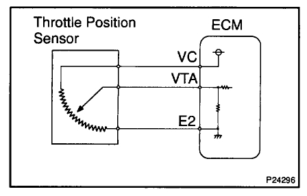
Will this work on a 3 pin sensor and how can I tell which pin is which?

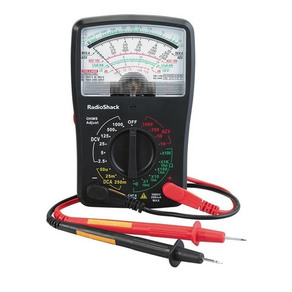
Which settings on the dial should this be checked with?
Saturday, October 14th, 2017 AT 6:05 PM

5 Replies

Tiny
STEVE W.
  • MECHANIC
  • 12,950 POSTS
A TPS is a variable resistor. Inside it has a wiper that rubs across a resistor. The three pins are easy The center is the wiper and is the signal to the ECM.
Two ways to test them.
First is while they are plugged in, You use a voltmeter set to volts DC. Then you probe into the back of the connector and measure the voltage that comes off the center pin. The voltage should be around.5 volt and rise to around 4-4.5 volts. The big thing is does the voltage rise smoothly and not drop out as you open the throttle.

The other way is to unplug the sensor. Then set the meter to ohms. Touch one probe to the center pin and the other to either outer pin. When you move the throttle the resistance will either rise or lower depending on which end pin you connected to.

One thing about testing them this way, an analog meter is the best type to use. That is because the digital meters tend to jump a lot and you could miss a problem because of that.
Was this
answer
helpful?
Yes
No
Sunday, October 15th, 2017 AT 10:05 PM
Tiny
NACHOBEAR
  • MEMBER
  • 4 POSTS
Thank you for the reply, can you tell me in detail what in each of those methods where each lead goes and also was your which response towards which video exactly?
Was this
answer
helpful?
Yes
No
Thursday, October 19th, 2017 AT 6:06 PM
Tiny
STEVE W.
  • MECHANIC
  • 12,950 POSTS
There are only 3 wires. One has 5 volts from the computer. One goes to ground at the computer and the third is the variable signal line that goes to the computer. The TPS itself works just like a light dimmer or volume control.
The outer pins are the 5 volts and ground and the middle is the signal.

Good video on testing.

https://www.youtube.com/watch?v=8KfKfImoIXg
Was this
answer
helpful?
Yes
No
Thursday, October 19th, 2017 AT 7:25 PM
Tiny
NACHOBEAR
  • MEMBER
  • 4 POSTS
Hi Steve just curious, is the sweep check the same as a continuity test, seems the same kinda

also it seems the reply you gave me below is for continuity if I am right

"The other way is to unplug the sensor. Then set the meter to ohms. Touch one probe to the center pin and the other to either outer pin. When you move the throttle the resistance will either rise or lower depending on which end pin you connected to."

I am still learning on how to do the sweep check, it seems it can be done with a scan tool for the live data when your in the graph mode though, what info I would like to find out if what am I trying to see if something is wrong when doing the sweep test, if I am doing this on a scan tool in live data graph mode (if this is even a good idea) or volt meter, if a tps sensor is bad is it going to have readings that won't go up properly and on a digital voltmeter saying that its an open loop?

What I also notice is the guy didn't really tell us where the leads go when we do the sweep check on a volt meter, or does the black lead not matter?

I might want to look for an analog meter but then unsure how to go about testing stuff with that as well
Was this
answer
helpful?
Yes
No
Saturday, October 21st, 2017 AT 5:27 PM
Tiny
STEVE W.
  • MECHANIC
  • 12,950 POSTS
The sweep test is looking for a constant circuit AND that the resistance change from closed to open throttle is smooth and constant.
The outer pins are connected to each end of the resistor. The center pin wipes across that.

The reading you get depends on how the TPS has failed.
On a graph a good sensor will have a constant slope across the sweep.

A bad one may have a break in the film and suddenly the graph will go open circuit, Or it will have a sudden change of voltage.

It may have spots where it is worn but not broken. On those there will still be a change but depending on the wear location you may see just a slight blip on the graph or scope or on an analog meter. BUT that blip could easily be fast enough that a digital meter won't update fast enough to catch it.

The black lead depends on which way you test. The way Paul was testing on the vehicle the black lead goes to ground.
Off the vehicle and doing a resistance check you would connect the lead to one of the outer pins. This test works the same way for many potentiometer type sensors, like a fuel level or light dimmer.
Was this
answer
helpful?
Yes
No
Saturday, October 21st, 2017 AT 10:31 PM

Please login or register to post a reply.

Sponsored links