Charging problem

Tiny
TYENDAGA
  • MEMBER
  • 2002 DODGE INTREPID
  • 2.7L
  • 6 CYL
  • 2WD
  • AUTOMATIC
  • 232,000 MILES
All the lights in my car are flickering then the battery light comes on. I have changed the alternator, battery, and starter and also replaced the PCM. I checked the voltage across the battery terminal and other various points of contact for output voltage readings with a result of 12-15vDC with fluctuation. I have checked the wiring harness for possible breaks or weak contacts and found nothing unusual. At this point, I am at a loss and decided to ask a second opinion. What have I missed?
Friday, May 3rd, 2019 AT 1:49 PM

9 Replies

Tiny
KASEKENNY
  • MECHANIC
  • 18,907 POSTS
Hi,

This is a voltage issue but it is odd because it appears you have replaced the main culprits.

I am slightly concerned about the fact that you see 12 volts at times because an alternator should not allow it to drop below 13.5 - 14.

The purpose of the 12 volt battery is to just smooth out the voltage spikes that you get from the alternator while you are accelerating and decelerating.

Even though I am a little concerned about that, I think your real issue is most likely the battery cables themselves at this point. Have you ever tested the resistance of the cables or performed a voltage drop test?

I attached the procedure so you can try this and ensure your cables are able to deliver the voltage that the battery and alternator are producing.

https://www.2carpros.com/articles/everything-goes-dead-when-engine-is-cranked
Was this
answer
helpful?
Yes
No
Saturday, May 4th, 2019 AT 5:05 PM
Tiny
TYENDAGA
  • MEMBER
  • 8 POSTS
That is an excellent test. I have not heard this one before. I will test this tomorrow and post my results. Additional information I could add is that prior to this symptom, I had noticed that the power steering reservoir cap was not sealing tight and fluid would leak out the cap onto the alternator itself. I replaced the alternator without testing it for defectiveness as it was covered and "fluid-logged" by this leaking over a long period of time. I also replaced the cap to correct the leak problem. Since the battery was completely flat, I assumed that the alternator was not producing the proper voltage/amperage to charge the battery properly. I replaced the battery with a fresh one just to eliminate the possibility of a dead cell adding undo strain to the new alternator. Since the problem was not resolved, and the voltage was fluctuating as it was, I assumed that this may have been a result from a faulty voltage regulator. Of course in the Intrepid, they could not have incorporated such a component within the alternator as most cars do so I swapped the PCM with a spare that I had which was in good working order when pulled from service. Again, the problem remains without change. The battery terminals appeared clean as did the starter and alternator contacts. However, I did not check for the resistance in the wires. Thank you very much for this suggestion and will test this in the morning.
Was this
answer
helpful?
Yes
No
Sunday, May 5th, 2019 AT 12:55 AM
Tiny
KASEKENNY
  • MECHANIC
  • 18,907 POSTS
Sounds good. Hopefully we get some results so we can at least move on or get it repaired. Thanks.
Was this
answer
helpful?
Yes
No
Sunday, May 5th, 2019 AT 5:38 PM
Tiny
CARADIODOC
  • MECHANIC
  • 33,729 POSTS
As a side note, Chrysler has a real long history of developing innovations that actually benefit the car owner, as opposed to GM and a few others that develop innovations that make them a lot of money. One of Chrysler's innovations was the "AC generator" first used in their 1960 models, and they copyrighted the term "alternator". GM didn't copy it until 1964. Chrysler also developed the electronic voltage regulator for 1970 models. GM copied it for 1972 models, but they put it inside their generator, as do most import manufacturers. This insures that when one part fails, you must buy both, meaning more than you need, unless you know how to diagnose the system and replace just what's defective. GM did the same thing with their "High-Energy Ignition, (HEI) system. It was a nice distributor, but at the time, no one knew how to diagnose it, so GM intended for it to be a drop-in unit replacement that needed no diagnosis. You bought every part in the ignition system, not just the one part that failed.

Charging a battery is a chemical reaction, and those take place faster as temperature goes up. To address that, Chrysler's first electronic voltage regulators had temperature compensation built in. That raised the target charging voltage a little in cold weather to help the battery charge. That is still done with the regulator in the Engine Computer, however, now the regulator has access to everything the computer knows. For example, the regulator can totally stop the alternator from working at wide-open-throttle when you might really need that five to ten horsepower used by the alternator. It can increase the alternator's output current when you turn on the rear defroster, rather than waiting for battery and system voltage to drop over time. It can anticipate the cycling on of the AC compressor and bump up charging voltage just in time to prevent the noticeable flicker of the lights caused by that sudden drain. If a load on the engine is causing coolant temperature to rise too high, it can cut back on the alternator to reduce the load on the engine.

Other manufacturers, mostly of imports, have tried doing the same thing, but when they hide the regulator inside their generators, they need additional wires running between it and the Engine Computer to share that data. Those extra circuits cause as much trouble as they solve.

Heat is always the deadly enemy of electronics, so the last place you'd want to stick a regulator, for reliability, is inside the generator where it sits right behind the radiator. In fact, most import failures are due to failed regulators, but since they're so involved to replace, you end up buying the entire generator Failure of Chrysler regulators has always been been very low. That doesn't mean they don't ever fail, but it is usually the last thing on the list of suspects. With the regulator inside the computer, about half of the charging system problems are related to the one wire that runs between the alternator and the computer, and the other half are for worn brushes inside the alternator. That doesn't leave much percentage for regulator failures. Guess I'll have to modify my numbers a little!
Was this
answer
helpful?
Yes
No
Monday, May 6th, 2019 AT 6:59 PM
Tiny
TYENDAGA
  • MEMBER
  • 8 POSTS
Caradiodoc. Your number are still correct. I have determined that the regulator, at least in my case, was not the faulting issue. In regards to alternator-incorporated regulator components, I remember when it was possible to replace the little black box outside the housing for a fraction of the price of a whole new alternator. However, by introducing it as an internal computer component, I see the potential for beneficial use in regulating additional systems in the process as well. Additionally, by placing the computer in a location away from the engine decreased the temperature in contrast to the alternator being within the range necessary for the drive belt to operate its armature. Heat is deadly to electronics is a true statement. Nice advancement of Chrysler's engineering.

When a new component or "option" is designed for a vehicle, specifically one primarily driven by a PLC circuit, it requires an additional 10 components (more or less) for the one "new" system to function property. By implementing the regulator within the computer system would in effect, eliminate the need for additional regulators to achieve the same goal. Like an one-for-all rather than a many-for one approach.

For KaseKenny. I checked the wires as described and did not find any abnormalities. However, I did notice that when I had a set of jumper cables attached to from a GMC Yukon to the Intrepid, the lights would not flicker until I removed the cables. Although I replaced the battery once, I played a hunch and again replaced the battery with another Brand new one and sure enough, it worked. I had the one I was using tested and even at full charge, it tested positive for a faulty cell. My only concern now is if the fluctuation in voltage caused the drainage in the first battery then one, where is the variable voltage coming from and two what is causing it? And will it kill this battery as well?

I will be monitoring this issue in the next few days for about a week or two and watch for drops in the battery charge capacity. For now, it seems to be working properly but I will report any new findings should they arise.

Thank you all very much for your input and your advice. It has been very informative and helpful in solving my conundrum. I will post again in a few days with an update.
Was this
answer
helpful?
Yes
No
Monday, May 6th, 2019 AT 8:58 PM
Tiny
TYENDAGA
  • MEMBER
  • 8 POSTS
Well, I have an update. I went to work today and all was good. However, on my way home, the battery light came on. Once I got in my driveway, I turned the car off then tried to turn it back on. Nothing. No lights or anything. It was like someone took the battery out of the car. I checked the voltage on the battery and it read 12.82vDC without running or key engaged. I disconnected the positive cable to the battery and placed one lead of the volt meter to the clamp and the other lead to the positive post of the batter while separated (as described in a previous post). It read 12.14vDC. Same for the negative cable at 12.14vDC. This reading was consistent rather the key was turned on or completely removed from the ignition switch. All connection points of each of the power cables are tight and clean. Also, I checked all the ground straps between the engine and the chassis. There are two of them and both appear in good shape. What could cause a voltage reading between the clamp and the post when the two are not connected? I have understanding in PLC logic circuits as well as electric circuitry and if the circuit is "broken", then there should be no continuity between the two points of contact. Oddly enough, when I replaced the cables back into their respective terminals, everything came back on and the car started up as if nothing was wrong? (Apparently, the disconnection of the battery reset the computer?) This is really beginning to make me think I either have a gremlin or a ghost in the machine? Lol (Note: Prior to testing the system, I jump started the car with my truck and it stared up. I disconnected the jumper cables and did a voltage check on the system still intact. It was doing the same thing with flickering lights and fluctuated between 11-15vDC. Once I completed all the testing and reconnected the battery, the car started on its own and voltage read a constant 13.84vDC without flux?)
Was this
answer
helpful?
Yes
No
Tuesday, May 7th, 2019 AT 3:28 PM
Tiny
CARADIODOC
  • MECHANIC
  • 33,729 POSTS
If you know about PLCs, you know much more than the average person. That will make this easier to explain.

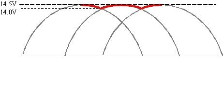
The alternator develops three-phase output, and once rectified, the pulses of output voltage are pretty smooth, but it's the battery that really smooths out that "ripple" voltage. In my sad drawing, the ripple voltage is 0.5 volt, the difference between the 14.0 and 14.5 volts. As the battery ages, the lead flakes off the plates, and the ability to smooth that ripple voltage goes away, even though that battery can still crank the engine just fine. Now the question is what voltage is the regulator going to see and respond to? Suppose the target charging voltage is 14.4 volts. If the regulator sees the 14.0 volts on its sensing wire, it's going to try to bump up alternator output to get to 14.4 volts, but in so doing, at times the 14.5 volts might go a little higher before the regulator detects that and corrects for it. You'll see that as the head light brightness flickering. The same thing happens when people disconnect a battery cable thinking that's a way to tell if the alternator is working! (Don't ever do that).

This has been a real big problem with GM vehicles after they redesigned their generators for the '87 model year. They use the same common switching circuit that turns field current on and off about 400 times per second, but for some reason their generators develop huge harmful voltage spikes that can damage the internal diodes and regulator, and interfere with computer sensor signals. They even use three zener diodes of the six to try to short out those spikes. Once again it's the battery that dampens and absorbs those spikes, and once again, they lose their ability to do that as they age. It is real common for people to go through four to six replacement generators in the life of the vehicle. To reduce that number of repeat failures, always replace the battery at the same time, unless it is less than about two years old. The old battery will work fine in an '86 or older model.

I wasn't clear on the tests you did when you disconnected the battery cables. Did you have just one off at a time? If so, I suspect your confusion came from the unexpected voltage when the ignition switch was off. In fact, before the mid '90s there was still the "IOD", (ignition off-draw) circuit that maintained the memories in some of the computers. That was allowed to be up to 35 milliamps for most car models. By the mid to late '90s, a lot of cars have an Engine Computer that needs up to 20 minutes to go to "sleep mode" after the ignition switch is turned off. During that 20 minutes they can draw up to three amps. This makes the old conventional testing method for a battery drain obsolete. I can describe the procedure, if you need it, on how to do the testing as before, with an amp meter in series with one battery cable, but you need to short the meter with a jumper wire for that 20 minutes and any time you change ranges on the meter. Any momentary break in the circuit wakes the computer up again and restarts the 20-minute timer.

It appears you found part of the problem with the old battery, but there is still something going on with the cables causing an intermittent problem. The goal now is to get it to act up, then be careful to not disturb anything that could cause the electrical system to come back to life. We need to get under the hood with the voltmeter with the problem occurring so there is something to diagnose. A test light works better for this type of problem because it requires current flow through it to work. All you need is a tiny carbon track for the voltmeter to pick that up and incorrectly say there's a good circuit there.

When the problem is occurring, turn on the head lights so current is trying to flow. That will make the following procedure show up the bad connection more effectively. Start with the negative meter probe, or test light's ground clip, right on the battery's negative post, and the other probe on the positive post. You'll find 12.6 volts if the battery is good and fully-charged. Now move the negative probe from the post to that cable clamp. You should find the same voltage. Move the positive probe from that post to that cable clamp, and expect to see the same voltage. If the voltage drops when you move a probe from one point to the next, that is the point of the bad connection.

Move the negative probe to a paint-free point on the body sheet metal or exposed bolt head. This type of problem is caused by a loose or rusted connection of the smaller negative battery wire at the body perhaps two or three percent of the time.

Now move the positive probe by following the smaller battery positive wire to the under-hood fuse box, and put the probe on the wire's terminal where you're likely to still find 12.6 volts. Finally, move that probe to the stud that terminal is bolted to. This is where you're going to drop to near 0 volts most of the time. Clean that terminal, then be sure that nut is tight. This one connection has been the cause of most intermittent dead electrical systems on every brand of car.

The large positive battery cable is only for the starter motor. It's the smaller one that puts the battery in the circuit to smooth ripple voltage, so a poor connection there is like removing the battery while the engine is running. The result then would be the flickering lights. The regulator is seeing the changing ripple voltage and is trying to keep up with it. By the time is responds appropriately, the voltage has already changed again. The regulator will have a nervous breakdown trying to maintain system voltage.
Was this
answer
helpful?
Yes
No
Tuesday, May 7th, 2019 AT 5:10 PM
Tiny
TYENDAGA
  • MEMBER
  • 8 POSTS
Interesting. I follow what you are saying though and will perform these tests tomorrow and update with the results. I will also attempt to conduct a continuity test on all the power leads to ensure there are no breaks or shorted wires anywhere too. I have already to a simplified extent but I will be a little more thorough with the testing. Thanks again for the input.
Was this
answer
helpful?
Yes
No
Tuesday, May 7th, 2019 AT 5:33 PM
Tiny
CARADIODOC
  • MECHANIC
  • 33,729 POSTS
Remember the type of problem you're looking for acts up because of the relatively high current flow through a less-than-perfect connection. If you plan on doing tests with an ohm meter, those never provide enough current to make the bad connection show. It's like standing on a garden hose and crushing it 99 percent closed. With the nozzle closed, you'll still have full pressure at the end, but there's no way you can get any water flow through it when the nozzle is opened. Opening the nozzle, or turning on the circuit, causes something to try to flow, and that is when the effects of the obstruction show up.

To say that a different way, the resistance is way too small to measure, but we can measure the results of that resistance, in this case, the drop in voltage.

Keep us updated on your progress.
Was this
answer
helpful?
Yes
No
Tuesday, May 7th, 2019 AT 6:03 PM

Please login or register to post a reply.

Sponsored links