Charging bypass cable direct to the battery?

Tiny
YYRK
  • MEMBER
  • 2006 CHRYSLER PACIFICA
  • 3.5L
  • 6 CYL
  • 4WD
  • AUTOMATIC
  • 160,000 MILES
I'm replacing my alternator and want to run a bypass charging cable direct to the battery. Is the A801 cable at the alternator what I need to disconnect?
Tuesday, December 9th, 2025 AT 2:05 PM

10 Replies

Tiny
CARADIODOC
  • MECHANIC
  • 34,350 POSTS
What are you trying to accomplish or modify? That cable has a fuse link wire in it. That shouldn't be bypassed.

What symptoms did the old alternator cause?

The two most common things we hear are the old alternator let the battery run down, and the new one does the same thing, and people want to install a replacement alternator with a higher output current. The first problem usually is caused by improper testing procedures or a misinterpretation of the results. I can help with that. The second one is most often the result of not understanding how the charging system works. Higher output won't help except when a lot of electrical equipment has been added on. An alternator with a higher maximum output won't develop any more current than the old one did.

I'm guessing you already have the wiring diagram. If not, let me know and I'll find one to post for you.
Was this
answer
helpful?
Yes
No
Tuesday, December 9th, 2025 AT 3:32 PM
Tiny
YYRK
  • MEMBER
  • 7 POSTS
Thank you very much for the reply. I have a few things I'm trying to accomplish.

1. Preventive maintenance. 160,000 miles. Live in am extreme climate (S. Nevada). Original alternator as far as I know.
2. Plan, partially, for a possible future audio upgrade.
3. I can hear some noise that sounds like it is coming from the alternator pulley/bearing?
4. It doesn't happen often, but there are times when the two positive cables are hot to the touch.

The alternator I purchased is an OEM (145A). No sure if I'll need a higher output, but for now I'm keeping it stock. And, yes, I pulled the wire diagram from Mitchell On Line.
Was this
answer
helpful?
Yes
No
Tuesday, December 9th, 2025 AT 3:56 PM
Tiny
YYRK
  • MEMBER
  • 7 POSTS
I do have a Kaiweets KM601 if you want me run any tests.
Was this
answer
helpful?
Yes
No
Tuesday, December 9th, 2025 AT 3:59 PM
Tiny
YYRK
  • MEMBER
  • 7 POSTS
Sorry, I meant the two 4 awg cables from/to the battery +.
Was this
answer
helpful?
Yes
No
Tuesday, December 9th, 2025 AT 4:01 PM
Tiny
YYRK
  • MEMBER
  • 7 POSTS
Just one last comment. Along with the alternator, I'm also replacing belt and tensioner.
Was this
answer
helpful?
Yes
No
Tuesday, December 9th, 2025 AT 4:36 PM
Tiny
CARADIODOC
  • MECHANIC
  • 34,350 POSTS
Dandy. There were three alternators available. A 120-amp, 145-amp, and a 160-amp. That's a huge increase over the optional 55-amp we had in the 1970s on cars with air conditioning.

The first thing to be aware of is the alternator is going to develop only the exact amount of current the electrical system needs, plus that to keep the battery charged. If the system needs 79 amps, for example, you could have a 1000-amp alternator but it's still only going to develop 79 amps.

The 120, 145, and 160 amps refers to the maximum output current the unit can develop while still maintaining no less than 13.75 volts. There is only one time the alternator is going to develop the full current it's rated at. That is the few seconds it takes to perform the "full-load output current" test during a charging system test. That takes just long enough to take the reading from the tester.

Where the potential problem comes in is that fuse link wire. That's a small section spliced into that A801 circuit. The wire is a smaller diameter making it the "weak-link-in-the-chain", and its insulation is designed to not burn or melt. Using my 1980 Volare as an example, that fuse link wire was one of three gauges depending on the size of the alternator installed at the factory. Part of the package that included FM radio, I got a bigger alternator and a bigger fuse link wire, but not the biggest one that was available. If I would install the largest alternator I could find, it's still only going to develop the needed current, and no more, ... Until I perform the full-load-output-current test. At that time the higher current will be greater than what the original fuse link can handle. That test is the only thing that can burn the fuse link out, (other than a badly-shorted alternator or the output stud was shorted to ground by a wrench). On most vehicles today that fuse is a standard fuse that's bolted into the under-hood fuse box. Those will blow instantly. Fuse link wires are more forgiving and take some time to overheat and burn open. That type is often used for motors that have a very high, but brief, start-up current.

In looking at your diagram, I don't see any reference to there being three optional fuse link diameters. They only show an 8-gauge wire spliced into the 4-gauge cable. That implies that fuse device will hold up to any of the three alternators, so that's one thing you don't have to worry about.

As for preventive maintenance, you do have high enough mileage were a failure can be expected, but the most common thing is worn brushes. Those will always start out as an intermittent problem. You'll see the voltmeter drop or a warning light or message pop up about the low voltage. That will typically last a minute or two at first. If you ignore it long enough, those periods of failure will become longer and longer, so you'll have a lot of warning. It looks like you have a version of the little silver Nippendenso alternator. I have that on a 1994 Grand Voyager. I was able to replace that brush assembly without removing the alternator from the engine. The part cost around $8.00 from a starter / generator rebuilder shop in town. If you can do this type of repair, replacing the brush assembly is much less expensive and it only takes a little longer than just replacing the entire alternator. I can help with that if it becomes necessary.

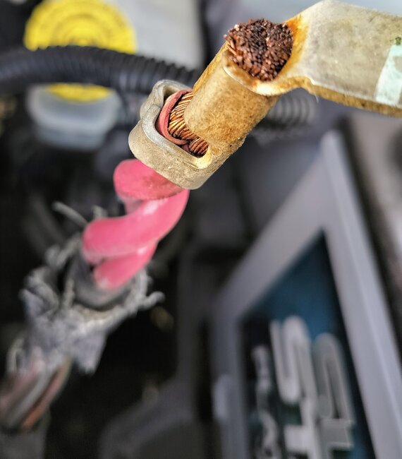
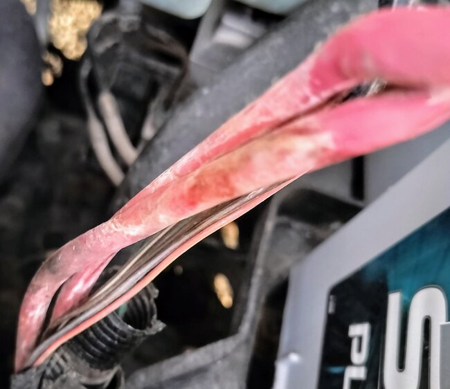
As for the hot cables, it would be interesting to know how much current is flowing through them. If you can find a shop with a tester that uses a clamp-on inductive pick-up probe, (most do), that will quickly tell you that, but only at that instant. The value only applies to what you have turned on at that time.

Without the professional tester, there are some things you can do with an inexpensive digital voltmeter. The main test is to look for an unacceptable "voltage drop" in those cables. That involves measuring the voltage right on the alternator's output stud, and at the battery's positive post, (not the cable clamp). Gotta be right on the post. The problem is you're taking two readings at two different times with a number of variables. The simple solution is to set the voltmeter to its lowest DC Volts range, usually 200 or 2000 millivolts, then put one probe on each of those two points. Logic dictates those are two places in the same circuit and the difference in voltage should be 0.00 volts, however, there's always a little resistance in the cables, splices, and connections. By measuring this way, you're only seeing the difference in voltages. Expect to see around perhaps 50 to 200 millivolts, but we don't want more than 0.40 volts. If it's higher than that, then we have to move the meter probes to different points to narrow down the cause that excessive voltage drop.

That reading will change as you turn on more loads. Lights, heater fan, and rear window defogger are some high loads that make the charging system work harder.

Another test the professional testers do is called the "ripple voltage" test. Basically, that will be "high", (bad), or "low", (good). That refers to the six or more "diodes" inside the alternator. If one of them fails, the most the alternator will be able to develop is exactly one third of its rated current. That isn't enough to meet the demands of the electrical system under all conditions, then the battery has to make up the difference as it slowly runs down over days or weeks. We'll discuss that more if it becomes necessary. The main diodes are in two groups of three. If one shorts in each group, that's when there's a dead short and the fuse link wires does its thing and burns open.

One last thing that I'll mention briefly is fuse link wires cause a real lot of confusion, mainly among very experienced mechanics. When they burn open, the last step is to create an arc that deposits carbon on the inside of the insulation. That carbon is more than enough for a digital voltmeter to falsely "see" voltage. This is where a simple, inexpensive test light will be much more accurate. By the way, replacement fuse link wire is available at any auto parts store. The common 12" piece is enough to be cut to make three or four repairs. You buy them according to the color of their insulation which denotes their current rating.

As for the noise, you can loosen the drive belt, then spin the pullies by hand to look for a noisy or rough one. A stethoscope works well for that too. All of those tools can be found at Harbor Freight Tools and most hardware stores.
Was this
answer
helpful?
Yes
No
Tuesday, December 9th, 2025 AT 4:56 PM
Tiny
YYRK
  • MEMBER
  • 7 POSTS
Thank you very much for the detailed response.

I also have a clamp meter (EM306B); not sure if that is the same as the inductive clamp you mentioned. I'll get some readings in the morning without much of a load, then also with the heater, aftermarket amp/stereo, lights, defroster running for comparison. It's going to be difficult because the two + cables are twisted together tightly and Chrysler combined into one crimped open terminal at the battery. Not sure I understand the wisdom in using the same cable; the starter cable, for both delivering a starting charge and switching to a battery charge cable when the car starts. Economically, yes, but I would never think of using the same circuit.

This brings around to one of my questions regarding the bypass cable. If my understanding is clear, wouldn't the bypass just completely eliminate that fusible wire as a potential issue now and forever? Just run my 1/0 cable to a MRBF with a 150A fuse block, then to the battery and be done. Later on, I can worry about an upgrade ground [/strap] with the appropriate ampacity.

If it turns out I need a HO alternator I'll be already have the infrastructure in place minus a properly sized fuse block. If not, no worries, I have some nice cabling and easily assessable fuse should I ever need to replace it.
Was this
answer
helpful?
Yes
No
Tuesday, December 9th, 2025 AT 6:50 PM
Tiny
CARADIODOC
  • MECHANIC
  • 34,350 POSTS
If you use a new, fatter wire with its own fuse, you should unbolt the original wire from the back of the alternator and seal that terminal from arcing against ground. To use both cables provides the opportunity for a shorted alternator to draw way too much current but neither fuse will blow. The excessive current can warp the plates in the battery and cause it to short. To be effective, you need to have all the current flowing through just the one fuse. That means just one cable.

GM and Ford did this for many years where they used the starter terminal as a convenient tie point for their generator output circuit. Starter current starts out at around 200 - 250 amps for an instant, then drops down once the motor starts spinning. The cables have to be able to handle that. Once running, that starter current goes to 0, and charging current takes over, but will always be less. The only difference with Chrysler's system is they place the voltage regulator inside the Engine Computer where it can know a lot more information and make charging decisions based on that. The system takes a couple of seconds after the engine is running, to turn on, so the starter and alternator currents are never competing or occurring at the same time.

You might be expecting too much from a larger alternator as far as increased loads, especially an amplifier. The bass notes create the biggest current demand, but charging systems are designed to respond relatively slowly to avoid flickering lights. Digital dashes are especially vulnerable to that, so on GMs, for example, the voltage regulators look at the 12 volts feeding the instrument cluster rather than looking at battery voltage to maintain system voltage. They don't care if the voltage fluctuates for the fuel pump, radiator fan, and things like that. They don't tolerate fluctuations to the dash display. Because the charging current is designed to adjust somewhat slowly, as in milliseconds instead of instantly, the electrical system relies on the battery to provide the instantaneous current demands while waiting for the charging system to catch up. This is another place where GM has had a huge problem since they redesigned their generators for the 1987 model year. Electrical system performance, and especially reducing the high number of repeat generator failures, is highly dependent on having a good battery with very low "internal resistance". That makes them able to supply the instantaneous high current pulses better than the generator, even a generator with much higher output current capacity.

A different approach is to use a very large capacitor right at the 12-volt supply to the amplifier. Capacitors are similar to an extremely small storage battery, and can provide just enough current to the amp when that current can't get through from the battery. No matter how fat a cable is used, there's always a little resistance in it. That's what impedes current flow. That resistance is very insignificant when running motors, injectors, ignition coils, and things like that. It is significant when we can hear the results of unsteady voltage.

As for your current probe, I have one too, but as I recall, it either doesn't have a DC Amps range, or it's very low. If yours can read DC amps in a high enough range, you do need to separate the cables so you can read each one independently. If you clamp around both together and get a very high reading, you won't know if that high current is flowing in just one or both cables. More likely you'll get a very low reading because current flowing in different directions in each cable will cancel each other out, then you'll only read the difference. A better approach is to read charging current right at the back of the alternator, or, in this case, on the starter cable. I'd be interested to know what you find. My guess is with the engine running and lights on, it should be less than 50 amps.

For the benefit of others researching this topic, be aware on newer vehicles, most use some type of current measuring circuit built into one of the battery cables. That circuit is used, in part, to reduce the charging rate for "absorbed glass mat", (AGM), batteries. Those don't use a liquid electrolyte like regular lead-acid batteries do. As such, it's harder for "off-gases" to dissipate. They want them to recharge slower to give that gas time to work its way out. With this circuit, the voltage to the electrical system can be maintained, while keeping the battery's charging rate low. Bypassing that circuit should only be done if a standard lead-acid battery is used for a replacement.
Was this
answer
helpful?
Yes
No
Wednesday, December 10th, 2025 AT 4:10 PM
Tiny
YYRK
  • MEMBER
  • 7 POSTS
Great information. Thanks again.

You are correct, my meter only does AC, so useless. I’ll have to purchase a DC capable meter.

Will definitely disconnect and disable the OEM cable when I get there. Watched a YT video earlier on replacing the stater just to see if the electrical was accessible without too much surgery. Would like to run a new 4 gauge wire to the starter and clean up/uncouple the connection at the battery with separate lugs for it and the wire going to the fuse box. Just a future project for now.

I’m not at all sold on the HO alternator. Still not sure if I need it. Looking at some preliminary amp usage in my audio system it is a lot lower than expected. Need to do more testing. I discounted the capacitor idea awhile back, but I’m starting to reevaluate. I need to find a reputable manufacturer that uses high quality caps; many of them look unprofessional nad marketed by questionable retailers. Was also looking at a small aux lithium battery in the back; something like a Maxwell.

I did a little online search and looks like the 2006 Pacifica doesn’t utilize any sensing function in the battery cable. Supposedly, circa 2010 things began to change in the industry.
Was this
answer
helpful?
Yes
No
Wednesday, December 10th, 2025 AT 10:35 PM
Tiny
CARADIODOC
  • MECHANIC
  • 34,350 POSTS
I didn't see any current sensing circuit either, but often people read these conversations first when they have a similar problem or car model. I like to include those tidbits of information to avoid problems if they follow our suggestions.

A cheaper alternative to buying a DC amp meter is to visit a nearby community college with an Automotive program and talk with an instructor. They're often looking for live work to give their kids real-world experience. They will have testers with quick, inductive probes. They'll usually let you stand right there to watch and to do the tests with all the variables you care to switch on or off. One thing to be aware of though, in my case, I only taught Electrical for eight weeks per year, four hours per day, and part of that time was spent in the classroom. That eight weeks is the only time we took in electrical work. We were so pressed for time that we did not do electrical work during my Brakes, Suspension and Alignment, or Engine Repair classes. Also, to do work outside of the subject we were teaching took work away from the shops that hired our graduates.

You can also look for a simple pointer-type amp meter that you hold alongside a wire. All of these inductive meters work by the magnetic field that is always formed around a wire when current flows through it. You still will need to separate the wire under test from any adjacent wires so you're reading the current in just the wire you're interested in.

To put your aftermarket amplifier in perspective, I used to have a home audio system rated at 10 watts per channel. That was plenty loud and sounded fine. Compare that to the typical Chrysler radio that can develop, as I recall, around 5 watts per channel. They also had two version of the Infinity system that used remote amplifiers. Unlike on GMs and Fords, all Chrysler radios put out speaker-level output. When amps are used, they are only for tone conditioning for the shape of the body. They do not increase volume or power. The minivans used small amplifiers bolted to the speakers. Besides the two speaker wires, they had the 12-volt and ground wires too, and those were piddly 16 gauge wires. That was sufficient to run those amps. I have that system in an '88 Grand Caravan.

Many of the car models used a separate amplifier mounted in the truck or under a seat. Those run all the speakers and have dedicated 12 gauge wires for power and ground. I have that in my '93 Dynasty. Those amps develop way more power than necessary, yet the wires don't need to be very fat. The amps do have capacitors in the power supply circuits to prevent a momentary drop in supply voltage, but those are hundreds of times smaller than the aftermarket ones sold by the stereo companies.

My point is you may have no need of a large capacitor at the amplifier. If you do, there's one more thing to consider that no one ever talks about. The purpose of those capacitors is to provide the instantaneous burst of current that is greater than what can get through the vehicle's wiring. When you turn the system off, that capacitor is going to discharge over a few seconds to as much as a minute or more. It all depends on the circuitry it's attached to. When power is switched back on, it is going to charge back up, and it wants to do that instantly. With nothing else in the circuit to limit that current flow, other than the little resistance in the wires and connector terminals, something has to be done to keep that current down to a safe level. There may be some small resistance built into the capacitor for that reason. When there is, it also reduces how much current can flow out. It's that tiny resistance that causes the fluctuations in voltage feeding the amplifier. If bad enough, (at high volume or heavy bass notes), we hear that as distortion. This is one time when I'd say it's acceptable to run a second, parallel wire to the amp. That may be just as effective at passing the needed current as having a capacitor for that job.
Was this
answer
helpful?
Yes
No
Thursday, December 11th, 2025 AT 2:46 PM

Please login or register to post a reply.