Code p406

Tiny
NASER NASER
  • MEMBER
  • 2006 DODGE CHARGER
  • V8
  • 2WD
  • AUTOMATIC
  • 176,000 MILES
Where should I start? Is it always the EGR automatically? Doesn't affect drivability.
Do you
have the same problem?
Yes
No
Tuesday, February 18th, 2020 AT 11:54 AM

16 Replies

Tiny
KASEKENNY
  • MECHANIC
  • 18,907 POSTS
This could be the EGR valve but it is actually a circuit code so that means we need to test the wiring as laid out in the diagram. They use what is called a break out box. This is not necessary, it only makes it easier to test the wiring.

Run through this test and let me know what you find. Thanks
Was this
answer
helpful?
Yes
No
+1
Tuesday, February 18th, 2020 AT 3:43 PM
Tiny
NASER NASER
  • MEMBER
  • 836 POSTS
Thanks. Will do that.
Was this
answer
helpful?
Yes
No
Wednesday, February 19th, 2020 AT 5:33 AM
Tiny
NASER NASER
  • MEMBER
  • 836 POSTS
Am not understanding what is it they are asking on number 2 where it says measure the resistance between F856 and the k34, meaning between what and what? In the third image.
Was this
answer
helpful?
Yes
No
Wednesday, February 19th, 2020 AT 9:03 AM
Tiny
KASEKENNY
  • MECHANIC
  • 18,907 POSTS
Good question. That’s asking you to check to see if the two wires between those two circuits are shorted together. You should get a resistance reading of OL on your meter or the equivalent depending on your meter which means it is out of limit of the meters capability, in other words there is so much resistance the meter can’t even read it because the two circuits are not touching each other. They should not have resistance between the two. If they have resistance between the two wires then that means they are shorted and are touching each other. Which needs to be repaired. If you have no resistance then you move onto the next step.
Was this
answer
helpful?
Yes
No
+1
Wednesday, February 19th, 2020 AT 10:12 AM
Tiny
NASER NASER
  • MEMBER
  • 836 POSTS
I see what you mean, but what I meant is where are those two wires? It talks about disconnecting the ego harness and the ppm harness which am not sure where is, and then, easier the resistance between the two wires, but it's vague which two wires.
Was this
answer
helpful?
Yes
No
Wednesday, February 19th, 2020 AT 10:15 AM
Tiny
KASEKENNY
  • MECHANIC
  • 18,907 POSTS
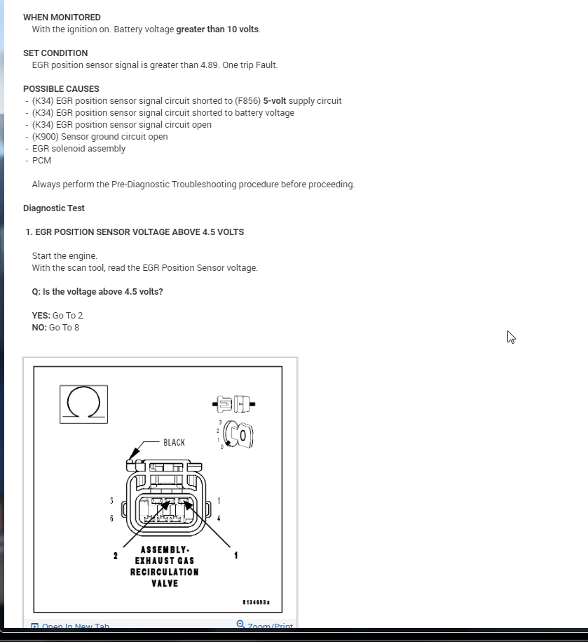
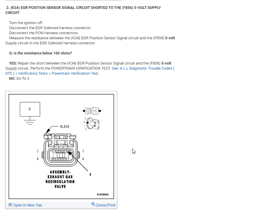
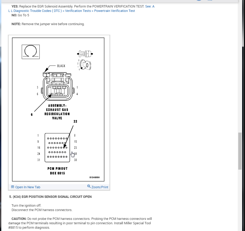
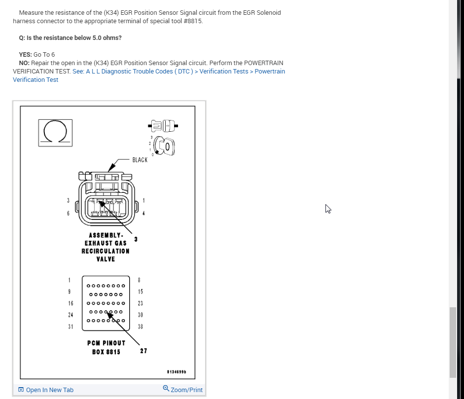
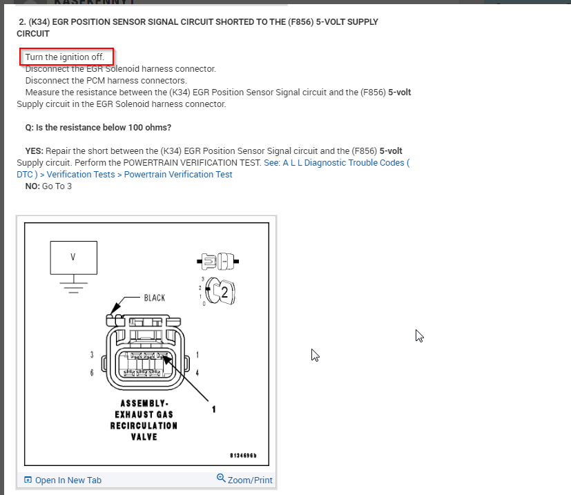
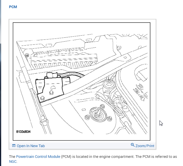
Sorry. It is actually pretty simple but when you don't read these things everyday they are confusing. You want to turn the key to the on position (notice the key image on the test and it is on the number 2) and then disconnect the PCM connectors (all of them as I think there are two on this engine). You want to measure for a resistance of just the wires being shorted. If you leave the PCM connected then you will be measuring resistance of the circuit board.

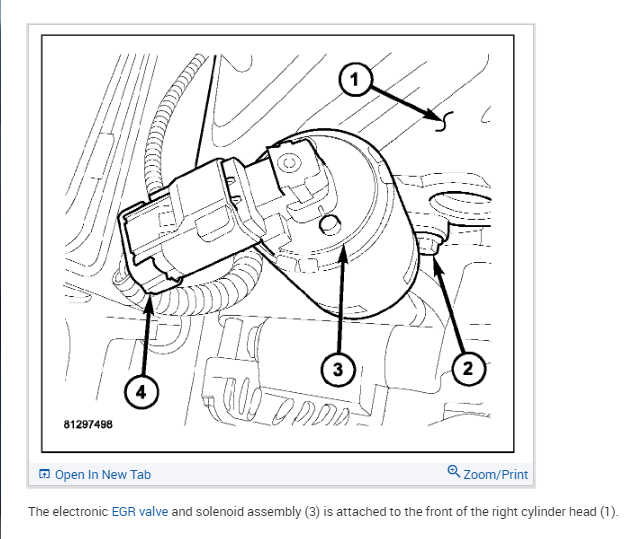
Then go to the EGR valve and disconnect the connector. Put your meter on ohms make sure your leads are in the correct selection of the meter for resistance measurements.

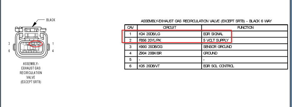
Then just put each lead on one of the pins shown in the diagrams attached here. The K34 circuit is in the first pin and the F856 is number 2 right next to it. Just make sure the connector is held in the same position as shown with the lock portion facing up so that you are not on the wrong circuits. You can look at the back of the connector at the wire colors to ensure they are the right pins.

Let me know what other questions you have. Thanks
Was this
answer
helpful?
Yes
No
+2
Wednesday, February 19th, 2020 AT 5:24 PM
Tiny
NASER NASER
  • MEMBER
  • 836 POSTS
I see, perfect, but why did you say turn the key on and then disconnect the ppm harness? Is it not the same as if the key was off since we are disconnecting ppm side and egg side?
Was this
answer
helpful?
Yes
No
Wednesday, February 19th, 2020 AT 5:29 PM
Tiny
KASEKENNY
  • MECHANIC
  • 18,907 POSTS
I am sorry. You are absolutely correct. That image with the key in the number 2 position is either for the next test or it is wrong.

Not sure why I didn't pick that up. You always test resistance of wiring with ignition off and it even tells you that on the first step.

Sorry for the confusion.
Was this
answer
helpful?
Yes
No
+2
Wednesday, February 19th, 2020 AT 6:28 PM
Tiny
NASER NASER
  • MEMBER
  • 836 POSTS
Thanks.
Was this
answer
helpful?
Yes
No
Wednesday, February 19th, 2020 AT 6:39 PM
Tiny
NASER NASER
  • MEMBER
  • 836 POSTS
Is the PCM under the cowl on passenger side?
Was this
answer
helpful?
Yes
No
Wednesday, February 19th, 2020 AT 6:41 PM
Tiny
KASEKENNY
  • MECHANIC
  • 18,907 POSTS
Correct. Passenger side in the corner of the fender and firewall.
Was this
answer
helpful?
Yes
No
+1
Wednesday, February 19th, 2020 AT 7:07 PM
Tiny
NASER NASER
  • MEMBER
  • 836 POSTS
So, for step one, measured EGR signal via scanner and was around 4.93v. Then step 2 disconnected harness to PCM and EGR and measured ohms between first and second pin and it stayed at 1 to the left of the display which I guess is Infiniti. Then step 3 connected PCM and measured volts via altimeter by touching pin 1 with one lead and and ground for the other lead and got 4.91v, but Q3 says is the voltage above 0? If yes, repair short. Does that make sense? I would have expected it to tell me to move on to the next step since this is the expected volts for pin 1, or am I missing something?
Was this
answer
helpful?
Yes
No
Friday, February 21st, 2020 AT 6:30 AM
Tiny
KASEKENNY
  • MECHANIC
  • 18,907 POSTS
This is tricky but it didn't say to reconnect the PCM harness in step 3. It told you to disconnect in step 2 so you should still have it disconnected for step 3. Then when you go to step 4, it tells you to connect the PCM connectors so this is when you should do it.

For step 3 the PCM supplies the 5 volts on this circuit but you are testing for a short to battery. So you want the supplied voltage removed to see if you are getting voltage from another source.

The fact that you have 4.91v, I suspect you will not have a short to battery but it is worth checking just to make sure.
Was this
answer
helpful?
Yes
No
+1
Friday, February 21st, 2020 AT 4:40 PM
Tiny
NASER NASER
  • MEMBER
  • 836 POSTS
I see, did that and it was 0 volts, went to step 4 and installed a jump wire and it was zero on the scanner, so therefore the egg is bad. Am I correct?
Was this
answer
helpful?
Yes
No
Friday, February 21st, 2020 AT 4:56 PM
Tiny
KASEKENNY
  • MECHANIC
  • 18,907 POSTS
As long as you did that with the ignition in the on position with the engine off. Then that is what I see as well.
Was this
answer
helpful?
Yes
No
Friday, February 21st, 2020 AT 5:41 PM
Tiny
NASER NASER
  • MEMBER
  • 836 POSTS
Yes it was on. Thanks!
Was this
answer
helpful?
Yes
No
Friday, February 21st, 2020 AT 6:15 PM

Please login or register to post a reply.

Sponsored links