Welcome to 2CarPros.
If the threaded part is still in the cylinder head, you need to get a spark plug extractor to remove it. There is actually a tool that is made to remove that. Also, there is a technical service bulletin regarding removal of a broken plug. I am going to provide the directions from the TSB. The attached pictures correlate with the directions. However, you will need the proper tooling.
______________________________________________
IGNITION SYSTEM - SPARK PLUG REMOVAL INSTRUCTIONS
TSB 08-7-6
04/14/08
SPARK PLUG REMOVAL INSTRUCTIONS - 4.6L
3V/5.4L 3V16.8L 3V
FORD:
2005-2008 Mustang
2004-2008 F-150
2005-2008 Expedition, F-Super Duty
2006-2008 Explorer,
F-53 Motorhome Chassis
2007-2008 Explorer Sport Trac
LINCOLN:
2005-2008 Navigator
2006-2008 Mark LT
MERCURY:
2006-2008 Mountaineer
This article supersedes TSB 08-1-9 to update Vehicle Applications, Service Procedure and Part List.
ISSUE
Some 2004-2008 F-150, 2006-2008 Mark LT, 2005-2008 F-Super Duty, Expedition, and Navigator, with 5.4L 3-V engine; 2005-2008 Mustang, 2006-2008 Explorer, Mountaineer, and 2007-2008 Explorer Sport Trac with 4.6L 3-V engine; 2005-2008 F-Super Duty, 2006-2008 and F-Stripped Chassis, with 6.8L 3-V engine may experience difficulty with spark plug removal. This may cause damage to the spark plug and leave part of the spark plug in the cylinder head. Affected engine build dates are as follows: 5.4L 3-V and 6.8L 3-V before 10/9/07, 4.6L 3-V before 11/30/07.
ACTION
Refer to the following Service Procedure for techniques to remove the spark plugs and extract broken spark plugs.
SERVICE PROCEDURE
The engine build date can be read on the left hand cam cover information sticker.
To remove spark plugs without damage, it is necessary to adhere exactly to this procedure before removal is attempted.
CAUTION
DO NOT REMOVE PLUGS WHEN THE ENGINE IS WARM OR HOT. THE ENGINE MUST BE AT ROOM TEMPERATURE WHEN PERFORMING SPARK PLUG SERVICE. REMOVING THE SPARK PLUGS FROM A WARM/HOT ENGINE INCREASES THE CHANCE THE THREADS COULD BE DAMAGED.
Spark Plug Removal Procedure
1. Remove the coil-on-plug assemblies and thoroughly blow out the spark plug wells and surrounding valve cover area with compressed air.
2. Back out the spark plugs no more than 1/8 to 1/4 of a turn. Using Motorcraft(R) Carburetor Tune-Up Cleaner, fill the spark plug well just above where the jamb nut hex sits (1/2 - 3/4 teaspoon). A minimum period of 15 minutes of soak time is required. The cleaner will wick down to the ground electrode shield and soften the carbon deposits in this time. DO NOT WORK the spark plug back and forth at this point.
NOTE
COMPLETELY REVIEW THE PRODUCT LABEL FOR THE MOTORCRAFT CARBURETOR TUNE-UP CLEANER PRODUCT - USE AT ROOM TEMPERATURE AND SHAKE WELL.
CAUTION
EXCESSIVE MOTORCRAFT(R) CARBURETOR TUNE-UP CLEANER, OR REPEATING THE PROCESS SEVERAL TIMES WITH TOO MUCH CLEANER FLUID, COULD INTRODUCE ENOUGH LIQUID VOLUME TO HYDRO-LOCK THE ENGINE.
CAUTION
DO NOT USE AIR OR POWER TOOLS FOR SPARK PLUG REMOVAL. SPARK PLUGS MUST ONLY BE REMOVED WITH HAND TOOLS.
3. Tighten, and then loosen the spark plug, working the plug back and forth. Some screeching and high effort may be noticed. The expected removal torque is about 33 lb-ft (45 N.M). Repeat the back and forth turning as needed until turning effort is reduced, and remove the spark plugs.
Pic 1
NOTE
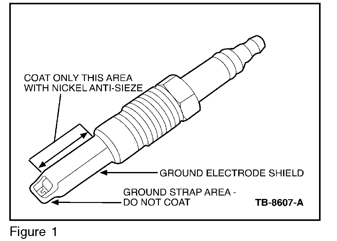
NEW PLUGS SHOULD BE INSTALLED USING A FILM COATING OF MOTORCRAFT HIGH TEMPERATURE NICKEL ANTI-SEIZE LUBRICANT ON THE GROUND ELECTRODE SHIELD. DO NOT COAT THE ELECTRODE STRAP. (Figure 1)
Separated/Broken Spark Plug Removal
If the spark plug separates after following the Spark Plug Removal Procedure, it will fail in one of three modes. Refer to the appropriate removal procedure as required.
Pic 2
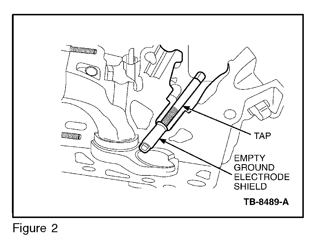
a. Mode 1: The ground electrode shield is left behind as an empty shell. (Figure 2)
pic 3
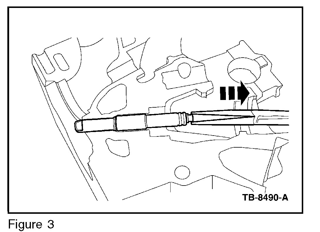
b. Mode 2: The entire porcelain insulator and ground electrode shield remains in the cylinder head. (Figure 3)
pic 4
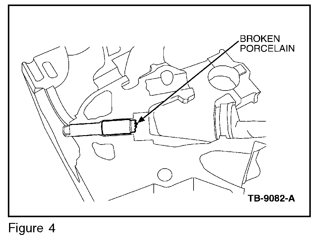
c. Mode 3: The upper section of porcelain broke off with remaining porcelain left inside the ground shield. (Figure 4)
pic 5
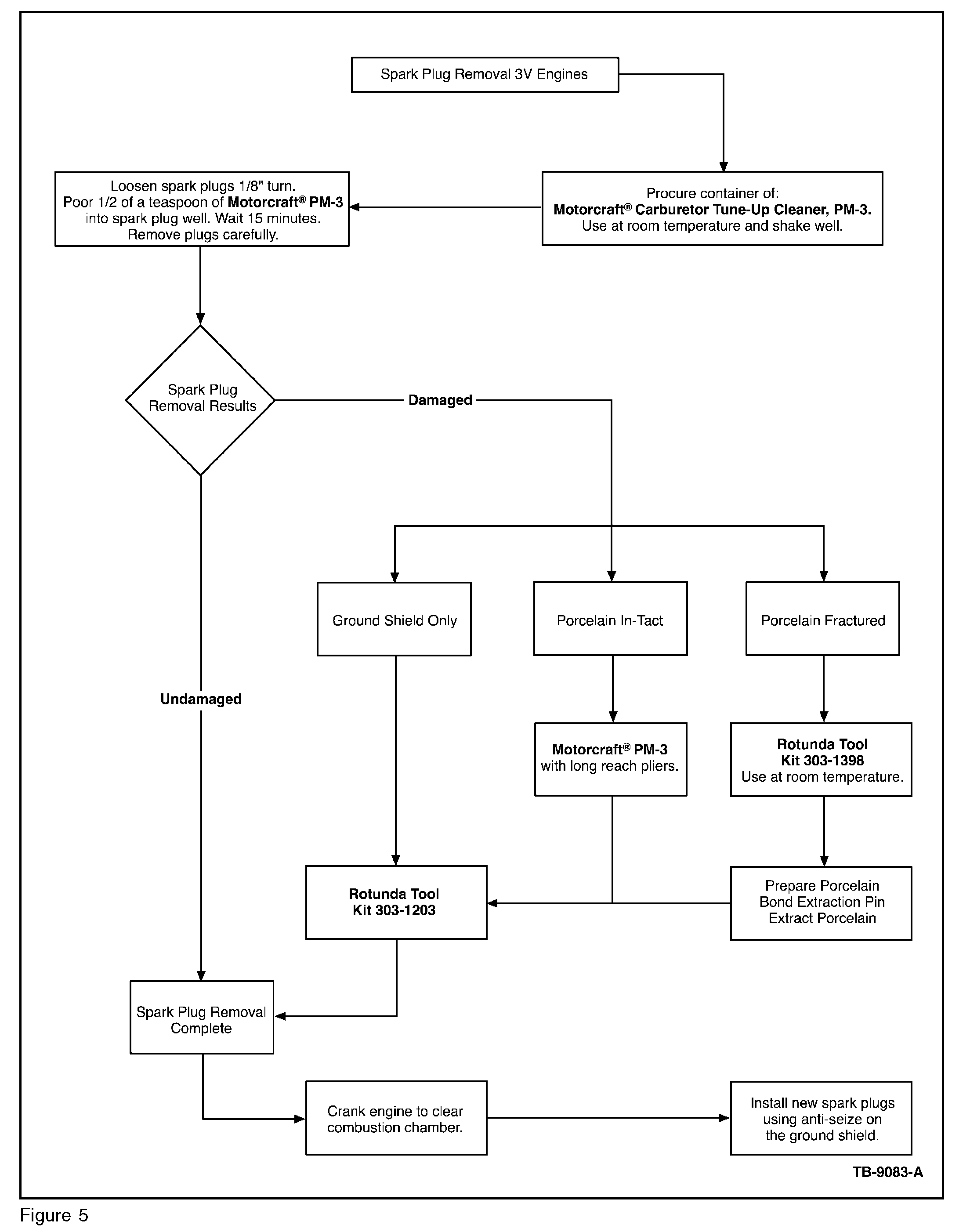
Flowchart of procedure. (Figure 5)
Mode 1 Procedure:
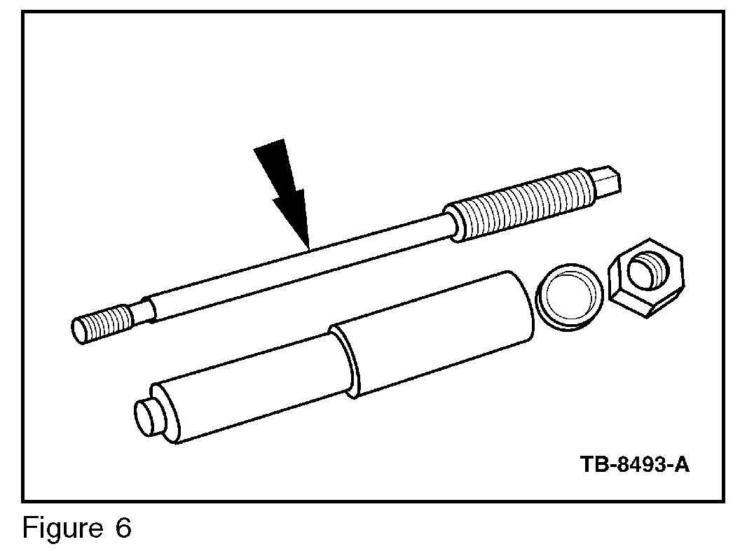
pic 6
Use Rotunda special service tool 303-1203 to remove an empty ground electrode shield from the cylinder head. (Figure 6)
NOTE
THIS TOOL IS ONLY DESIGNED TO WORK WITH AN EMPTY GROUND ELECTRODE SHIELD. IF PORCELAIN REMAINS, PROCEED TO MODE 2 OR 3 REMOVAL.
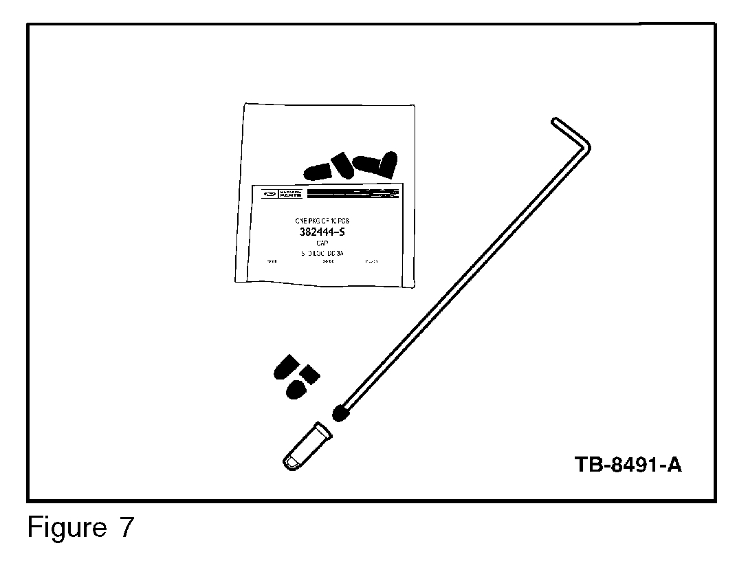
Pic 7
1. Modify vacuum cap to a 3/8" (10 mm) length for each ground electrode shield that needs to be removed. (Figure 7)
2. Use the installation rod (J) provided with service tool 303-1203 update to install the modified vacuum cap. Push the cap into the ground shield down to the electrode strap. This will plug and protect the combustion chamber from contamination. (Figure 7)
3. Thread-tap the ground electrode shield using a 9.0 x 1.0 mm plug tap (tap profile is about 3-4 reduced diameter threads on the tip end).
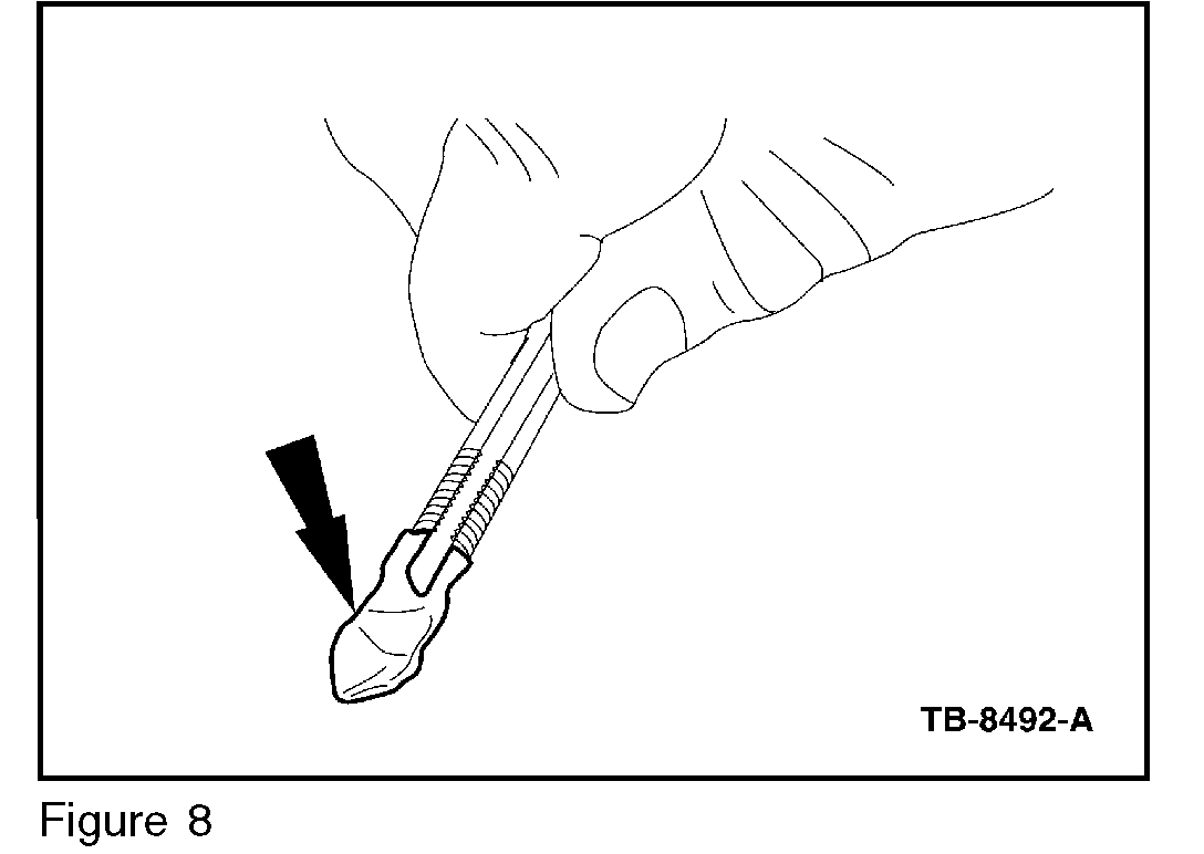
Pic 8
a. Coat the end of the tap with general purpose grease. (Figure 8)
b. Turn the tap about 3 to 4 turns into the ground electrode shield. Back the tap up frequently to break chips and avoid cut material from coiling-up in the spark plug well. A tap socket adaptor (K) is provided with service tool 303-1203 update to connect the tap to a 3/8" socket drive.
CAUTION
DO NOT ATTEMPT TO REMOVE THE GROUND ELECTRODE SHIELD WITH THE TAP AND WRENCH. THE TAP MAY BREAK IF THIS IS ATTEMPTED.
Pic 9
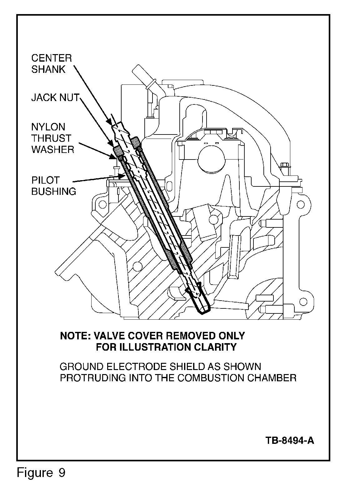
4. Thread Rotunda special service tool 303-1203 into the ground electrode shield. (Figure 9)
a. Install the stepped end of the tool pilot bushing into the spark plug well ensuring it bottoms out.
B. Screw the center shank into the ground electrode shield. Do not over tighten the shank, to prevent thread stripping.
C. Install the nylon washer and jack nut until finger tight.
D. Turn the jack nut until the ground electrode is freed from the cavity and withdraw the tool assembly.
NOTE
NEW PLUGS SHOULD BE INSTALLED USING A FILM COATING OF MOTORCRAFT HIGH TEMPERATURE NICKEL ANTI-SEIZE LUBRICANT ON THE GROUND ELECTRODE SHIELD. DO NOT COAT THE ELECTRODE STRAP.
Mode 2 Procedure:
1. Add an additional 1/2 teaspoon Motorcraft Carburetor Tune-Up Cleaner fluid into spark plug well and allow 15 minutes of soak time.
2. Using long-reach nose pliers grasp and remove the porcelain with an up and down motion taking care not to fracture the porcelain.
3. Refer to Mode 1 Procedure to remove the remaining ground electrode shield from the cylinder head.
Mode 3 Procedure:
CAUTION
DO NOT DRIVE PORCELAIN DOWN INTO THE GROUND SHIELD WITH A PUNCH AS FRAGMENTS MAY ENTER THE COMBUSTION CHAMBER.
Pic 10
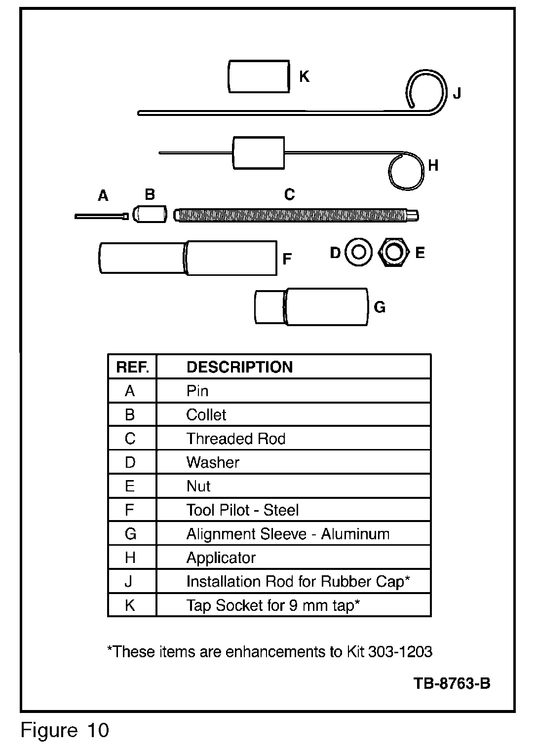
Use Rotunda special service tool kit 303-1398 to remove porcelain broken inside the ground electrode shield. (FIGURE 10)
Porcelain Removal - Preparation
CAUTION
THE ENGINE AND THE BONDING ADHESIVE MUST BE ROOM TEMPERATURE OF 70 °F (21 °C) OR HIGHER FOR PROPER CURE AND BOND STRENGTH. VERIFY EXPIRATION DATE OF ADHESIVE.
CAUTION
DO NOT REUSE PINS. THIS ENSURES THE CORRECT SURFACE CHARACTERISTICS FOR BONDING.
1. Remove any remaining electrode material from broken porcelain with long nose reach pliers.
2. Spray Motorcraft Metal Brake Parts Cleaner into the porcelain hole for 2-4 seconds using the straw nozzle supplied with the brake cleaner can.
Pic 11
pic 12
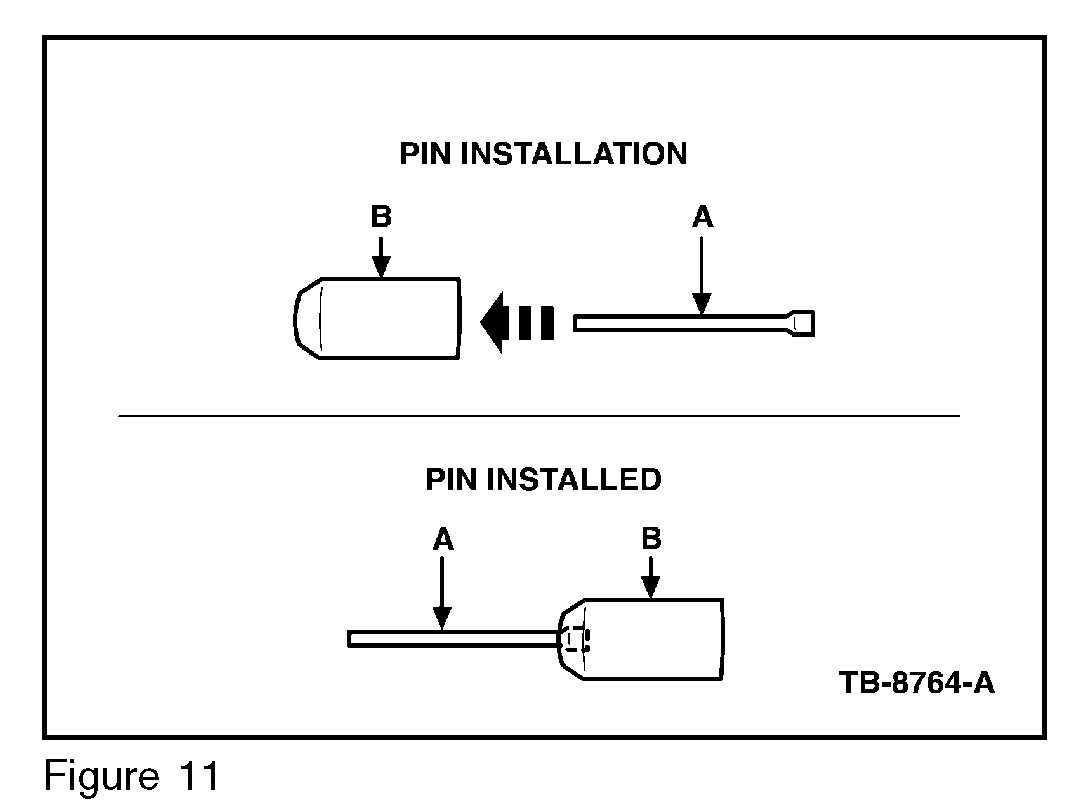
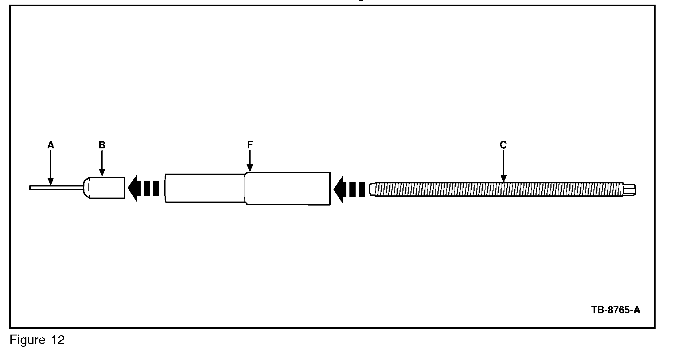
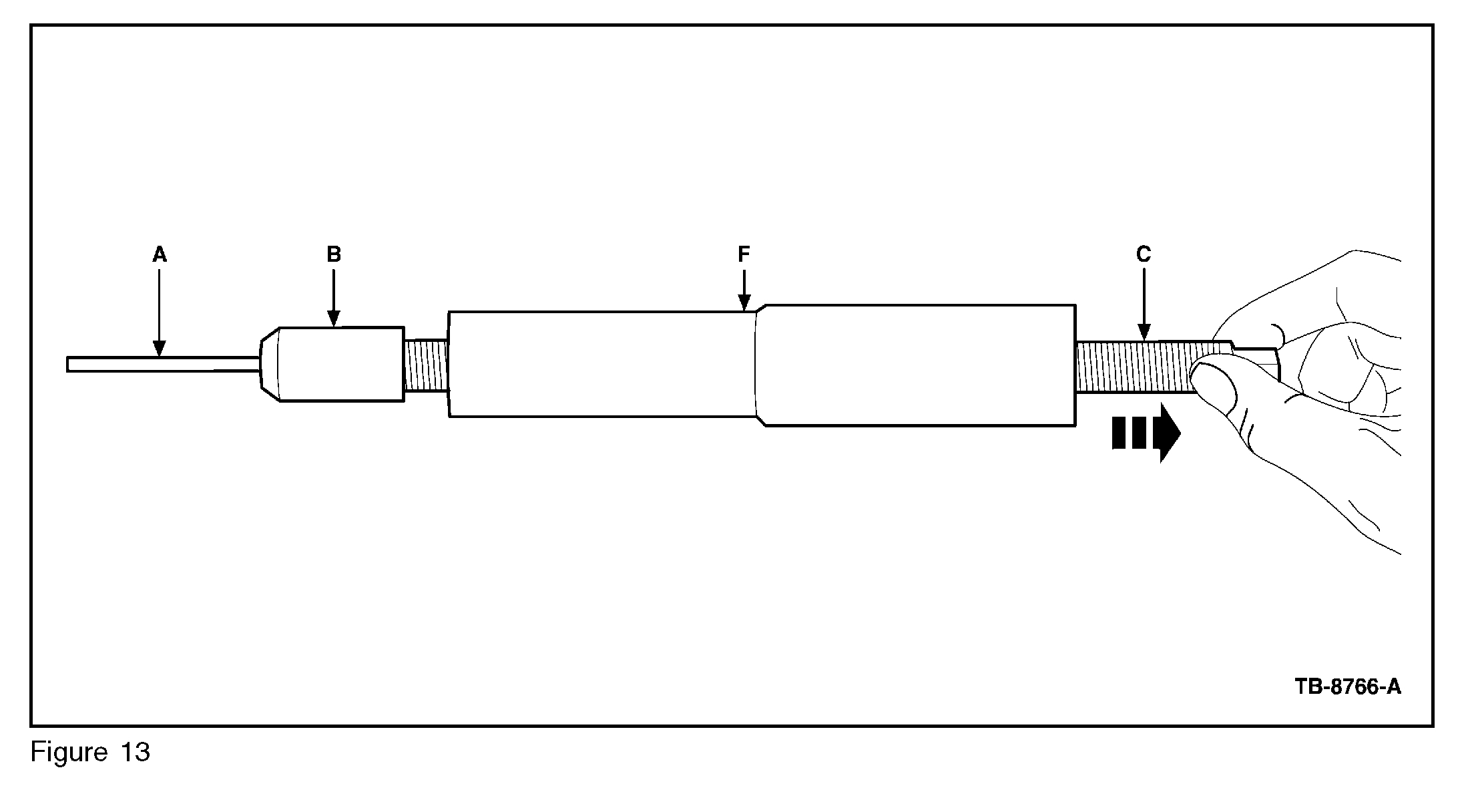
3. Insert a pin (A) into the collet (B). Screw the collet onto the threaded rod (C). Install the assembled collet, pin, and threaded rod into the steel tool pilot (F). (Figures 11 and 12)
pic 13
pic 14
4. Retract the collet and pin into the steel tool pilot, protecting the pin. (Figures 13 and 14)
NOTE
PIN TIP DAMAGE OR BENT PINS WILL PREVENT INSERTION INTO THE PORCELAIN.
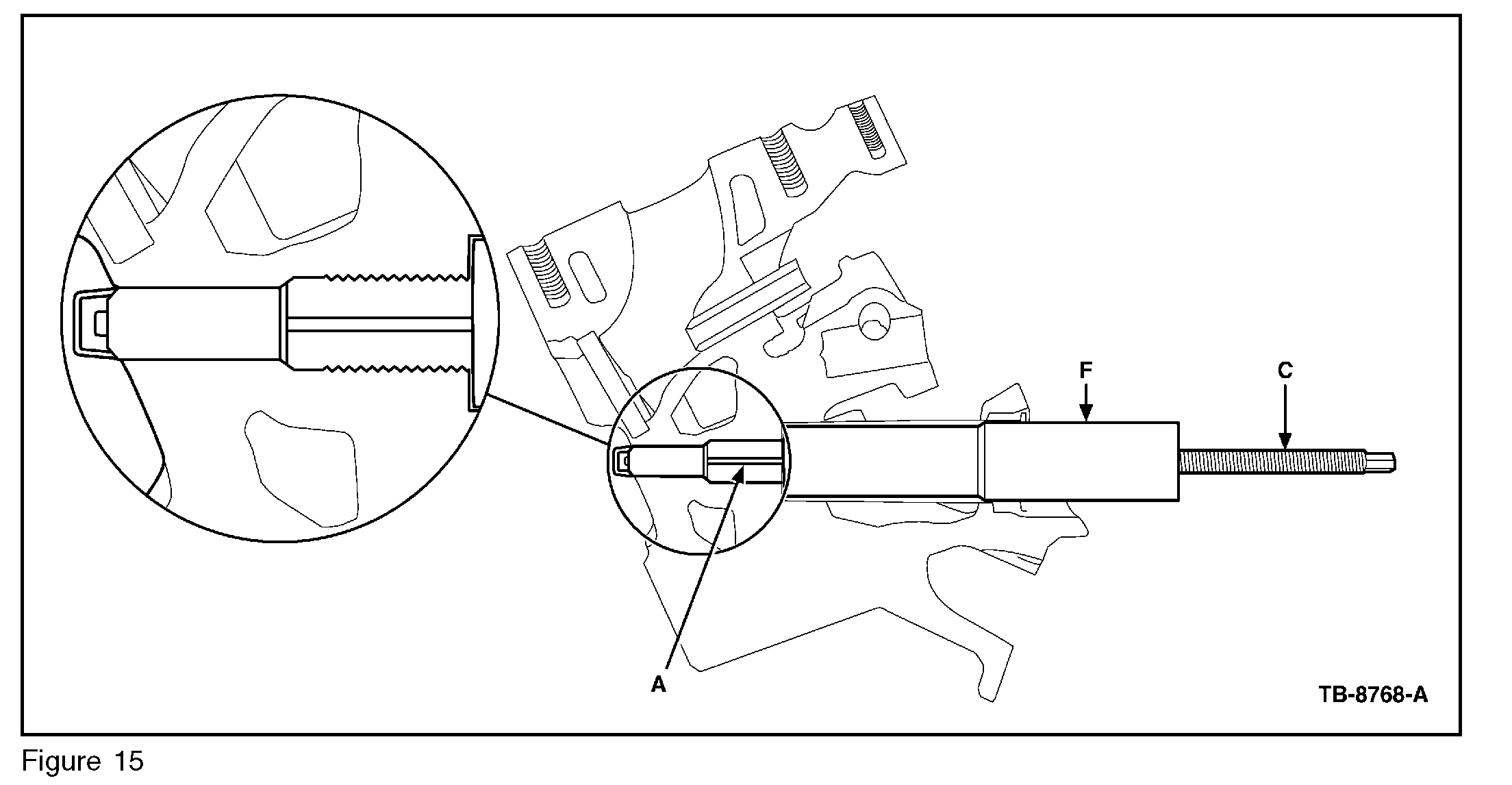
Pic 15
5. Insert the completed assembly into the spark plug well and fully engage the pin into the porcelain. (Figure 15)
6. Spray Motorcraft(R) Metal Brake Parts Cleaner 2-4 seconds between the spark plug well and steel tool pilot. The steel tool pilot must be lifted up approximately 1/2" to allow brake cleaner to flood the porcelain and pin.
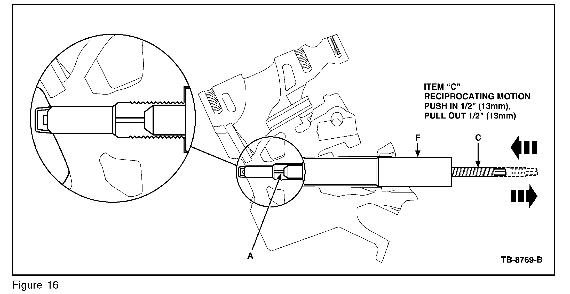
Pic 16
7. Scrub the porcelain inside diameter by moving the threaded rod up and down vigorously. Take care making sure the pin does not disengage the porcelain. (Figure 16).
8. Repeat Steps 6 and 7.
9. Remove the tool assembly. Again flood the porcelain with Motorcraft(R) Metal Brake Parts Cleaner for 2-4 seconds, then blow out the entire spark plug well and porcelain with dry compressed air.
NOTE
CLEAN AND DRY COMPONENTS ARE KEY TO BONDING THE PIN TO THE PORCELAIN.
10. Repeat Steps 1-9 to prepare remaining porcelain fragments as needed.
11. Disassemble the collet and pin from the threaded rod. Dry the tools thoroughly with dry compressed air.
Porcelain Removal - Bonding Process
CAUTION
USE CARE TO PREVENT BONDING AGENT FROM CONTACTING THREADS IN CYLINDER HEAD.
NOTE
WORKING TIME LIMIT OF LOCTITE(R) 638(TM) RETAINING COMPOUND IS 5 MINUTES.
Pic 17
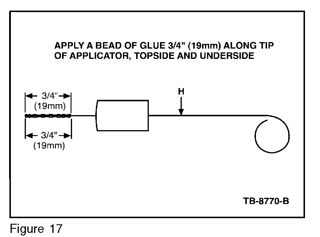
1. Apply two 3/4" (19 mm) long stripes of Loctite(R) 638(TM) to opposite sides of a clean and dry applicator (H). Excessive amounts of Loctite(R) 638(TM) are being used if it drips off the applicator. (Figure 17)
2. Insert applicator into the porcelain and move applicator up and down 1/2" (13 mm) while turning to spread the Loctite 638TM on the inside of the porcelain. (Figure 18).
3. Add additional Loctite(R) 638(TM), repeating Steps 1 and 2.
4. Clean the applicator with Motorcraft(R) Metal Brake Parts Cleaner before the bonding agent starts to cure.
5. Reassemble a dry and clean collet and pin assembly.
6. Apply two 3/4" (19 mm) long stripes of Loctite(R) 638(TM) to the pin. Excessive amounts of Loctite 638TMare being used if it drips off the pin.
7. Retract the collet and pin into the steel tool pilot to protect the Loctite(R) 638(TM) coated pin.
8. Insert the completed assembly into spark plug well and fully engage the pin into the porcelain with a twisting motion to spread the bonding agent.
9. Add additional Loctite 638TM, repeating Steps 6-8.
Pic 18
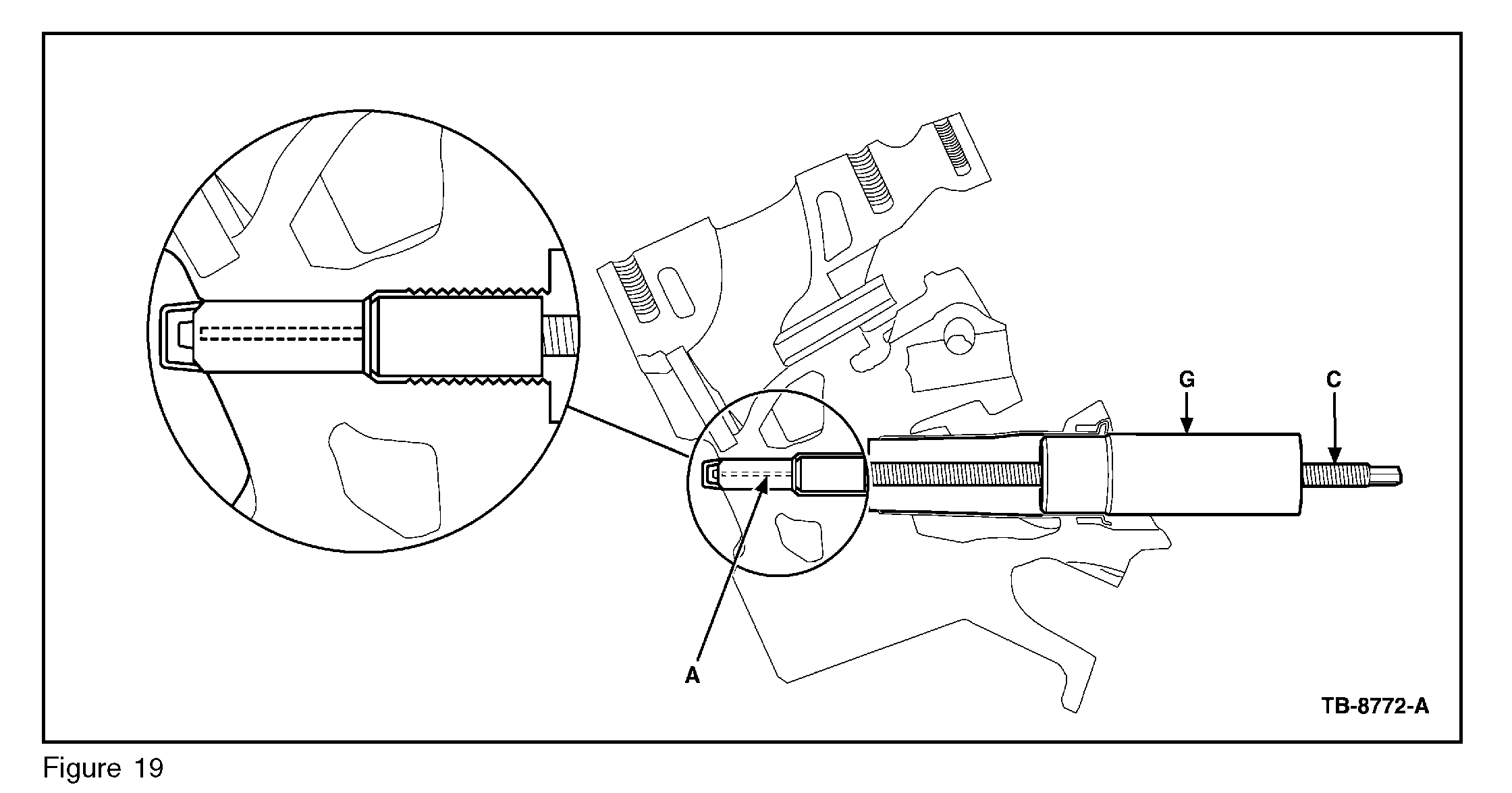
10. Leave the pin fully inserted in the porcelain while the adhesive cures. Replace the steel tool pilot with the aluminum alignment sleeve (G), Figure 9, to support the threaded rod while the adhesive cures if additional porcelain fragments are present in other cylinders. (Figure 19).
CAUTION
A MINIMUM 1 HOUR CURING TIME AT 70 °F (21 °C) DEGREES IS REQUIRED BEFORE EXTRACTION IS ATTEMPTED.
11. Allow the Loctite(R) 638(TM) to cure for a minimum of one hour at 70 °F (21 °C).
12. Repeat the bonding process for remaining cylinders as needed.
Porcelain Removal - Extraction
1. After a minimum of one hour curing at 70 °F (21 °C), install the steel pilot tool over the threaded rod.
2. Install the washer and jack nut until finger tight against the tool pilot bushing.
CAUTION
ONLY THE STEEL PILOT TOOL IS ACCEPTABLE FOR USE IN PORCELAIN REMOVAL.
3. While holding the end of the threaded rod with a wrench, tighten the jack nut until the porcelain is free of the ground electrode.
4. Refer to Mode 1 Procedure to remove the remaining ground electrode shield from the cylinder head.
NOTE
NEW PLUGS SHOULD BE INSTALLED USING A FILM COATING OF MOTORCRAFT HIGH TEMPERATURE NICKEL ANTI-SEIZE LUBRICANT ON THE GROUND ELECTRODE SHIELD. DO NOT COAT THE ELECTRODE STRAP. (FIGURE 7)
Porcelain Removal - Pin Slipped Out
In the unlikely event that the pin does not remove the broken porcelain, this process can be repeated.
Key elements to success are:
Clean and dry porcelain
Sufficient Loctite 638TM Retaining Compound spread uniformly
Loctite(R) 638(TM) cure time and temperature
Preventing the threaded rod from rotating while removing the porcelain
Replacement Supplies
Replacement kit components and additional kit consumables (Loctite(R) 638TM Retaining Compound and pins) can be obtained by calling 1-800-ROTUNDA, Option 5.
_____________________________
Let me know if this helps or if you have other questions.
Take care,
Joe
Images (Click to make bigger)
Friday, July 19th, 2019 AT 8:01 PM