Hi and thanks for using 2CarPros.
Here are the directions for timing belt replacement. It includes the procedures and timing mark indicators. I attached all of it in case you need it. All pictures correlate with these directions.
1993-1995 MODELS
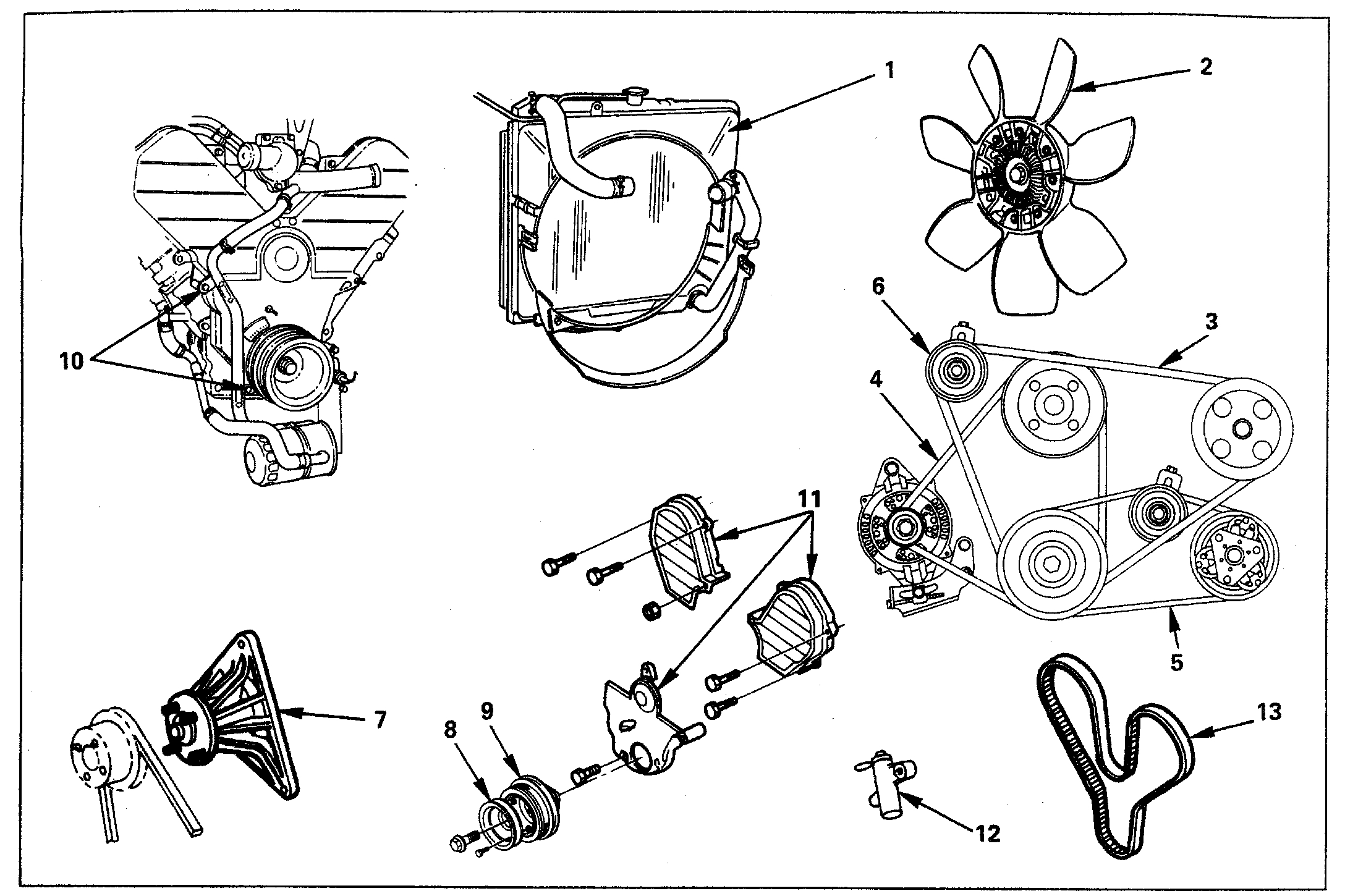
See picture 1
REMOVAL STEPS
Preparation: Battery ground cable
1. Radiator upper fan shroud
- Remove from radiator.
2. Cooling fan assembly
- Remove four nuts, then the cooling fan assembly.
3. Power steering pump drive belt
4. Air Conditioning compressor drive belt
5. Generator drive belt
6. Power steering pump drive belt
7. Fan pulley assembly
8. Crankshaft pulley assembly
9. Crankshaft pulley assembly
- Using special tool J-8614-O1, hold crankshaft pulley.
- Remove center bolt, then the pulley.
10. Oil cooler hose
- Remove two cooler hose bracket fixing bolts on the timing cover.
11. Timing belt cover
12. Pusher
CAUTION:
- The pusher prevents air from entering the oil chamber. Its rod must always be facing upward.
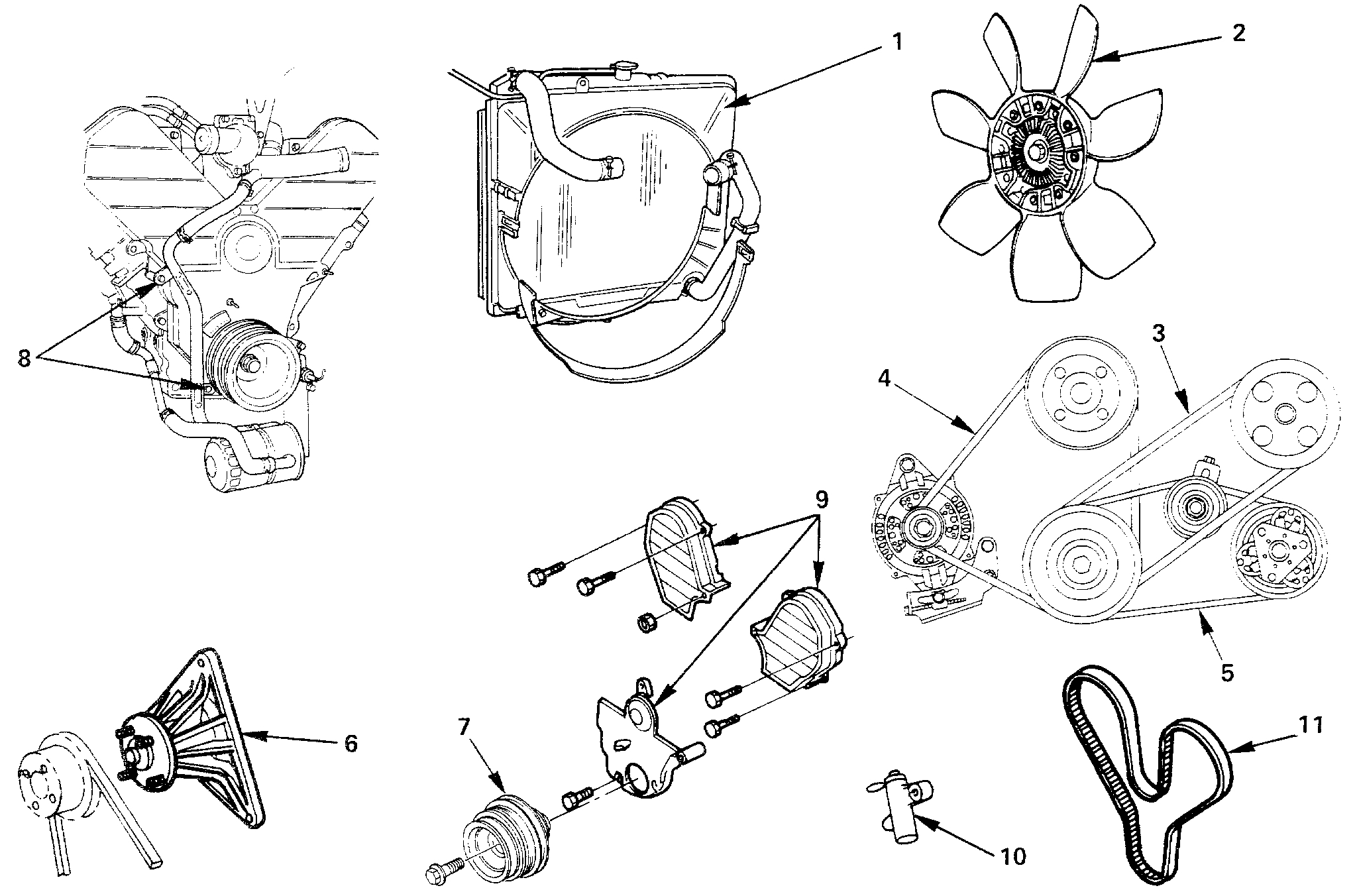
See picture 2
INSTALLATION STEPS
To install, follow the removal steps in the reverse order.
13. Timing belt
CAUTIONS:
- Do not bend or twist the belt, otherwise its core could be damaged. The belt should not be bent at a radius less than 3Omm.
- Do not allow oil or other chemical substances to come in contact with the belt. They will shorten the belt life.
- Do not attempt to pry or stretch the belt with a screwdriver or any other tool during installation.
- Store timing belt in a cool and dark place. Never expose the belt to direct sunlight or heat.
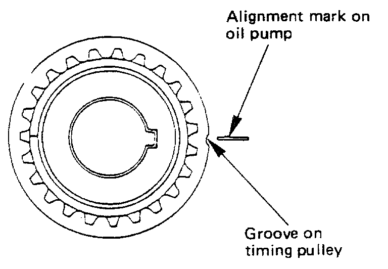
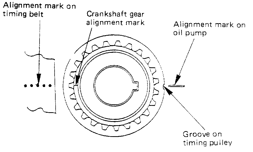
See picture 3
1) Align groove of crankshaft timing pulley with mark on oil pump.
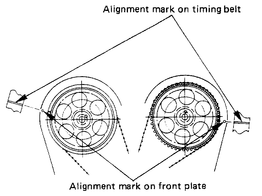
See picture 4
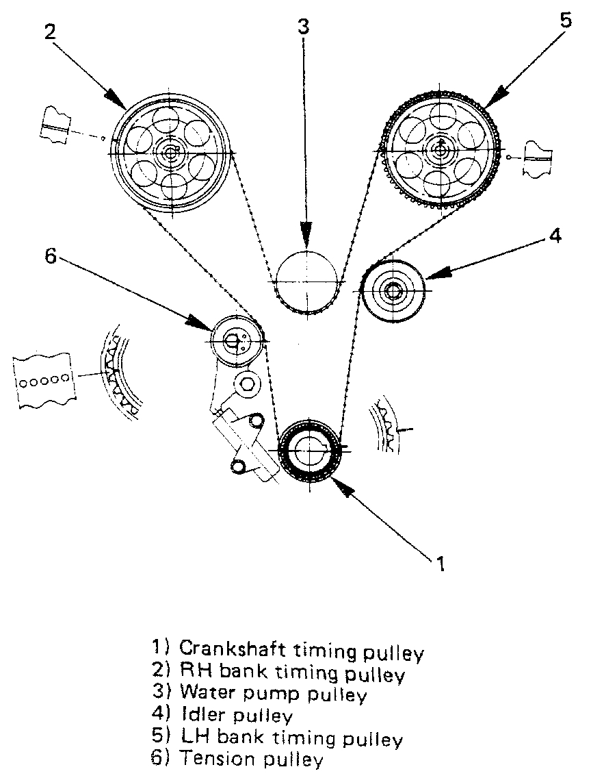
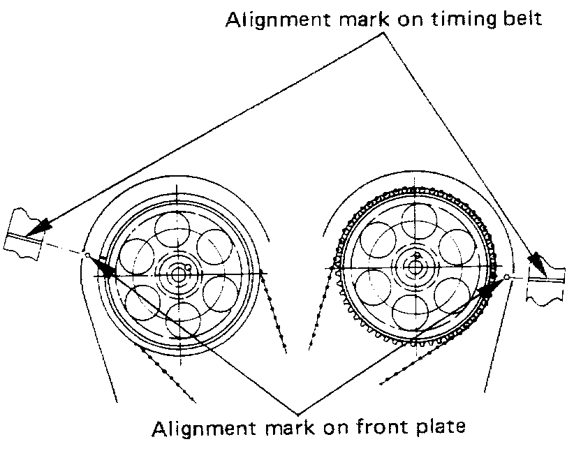
2) Align the marks on the camshaft timing pulleys with the corresponding dots on the front plate.
NOTE:
- When timing marks are aligned, no pistons will be on T.D.C.
See picture 5
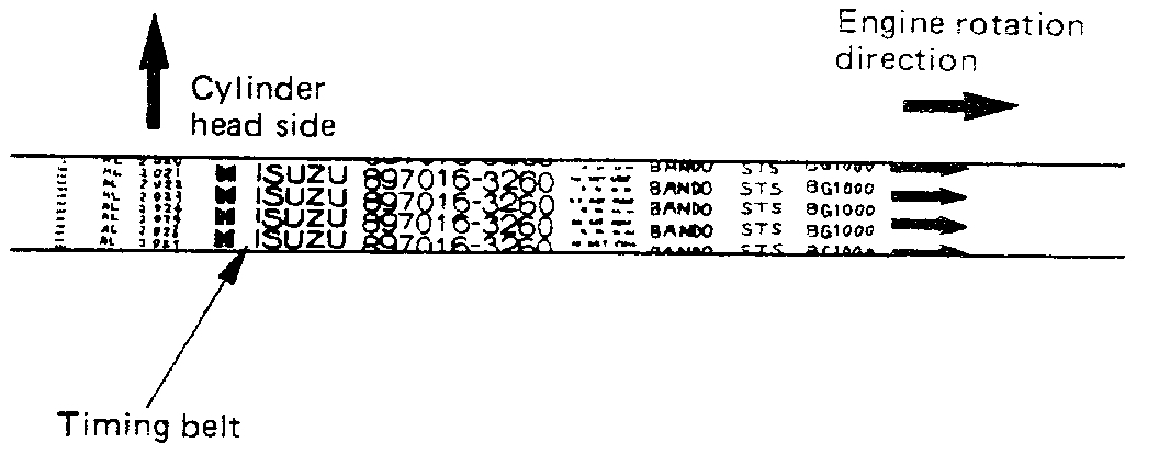
3) Install timing belt. Align the dotted alignment mark on the timing belt with the mark on the crankshaft gear.
See picture 6
See picture 7
NOTE:
- For correct belt installation, the letters the belt must be able to be read as viewed from the front of the vehicle. It is recommended for easy installation that the belt be secured with double clips after it is installed to each pulley.
See picture 8
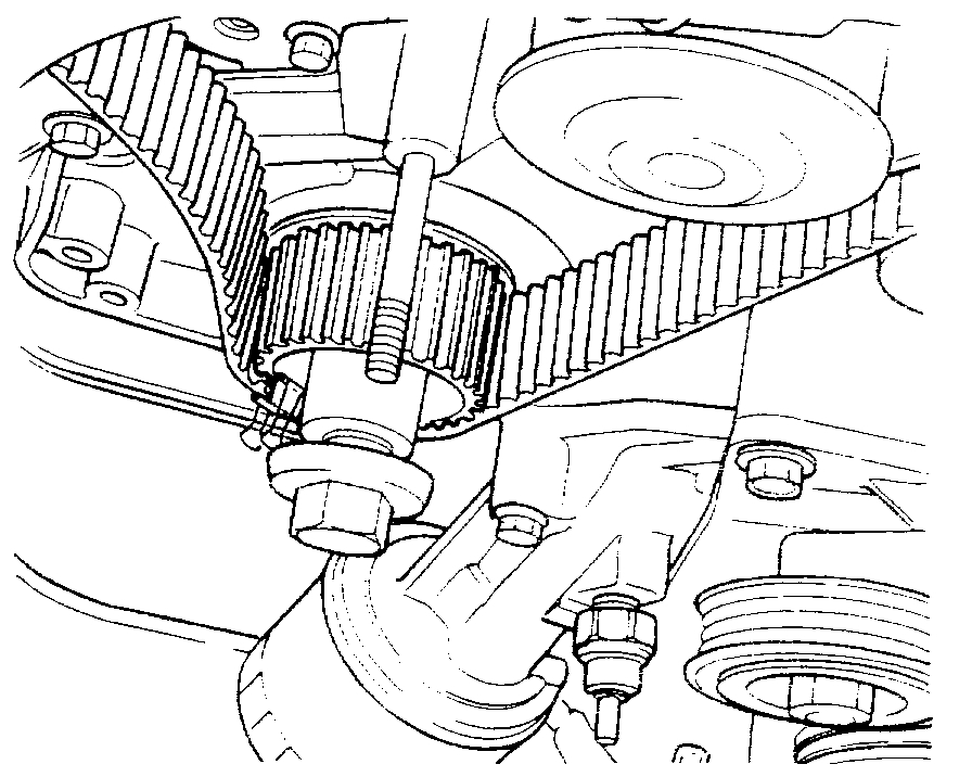
4) Align the alignment mark (white line) on the timing belt with the alignment mark on the RH bank camshaft timing pulley (on the left side as viewed from the front of the vehicle Secure the belt with a double clip.
See picture 9
5) Turn the crankshaft counterclockwise to remove the belt slack between the crankshaft timing pulley and the RH bank camshaft timing pulley.
6) Install the belt on the water pump pulley.
7) Install the belt on the idler pulley.
See picture 10
8) Align the alignment mark (white line) on the timing belt with the alignment mark on the LH bank camshaft timing pulley. If the belt is difficult to install turn the camshaft pulley slightly counterclockwise.
9) Install crankshaft pulley temporarily and tighten center bolt by hand (do not use a wrench). Turn the crankshaft pulley clockwise to give some slack between the crankshaft timing pulley and the RH bank camshaft timing pulley.
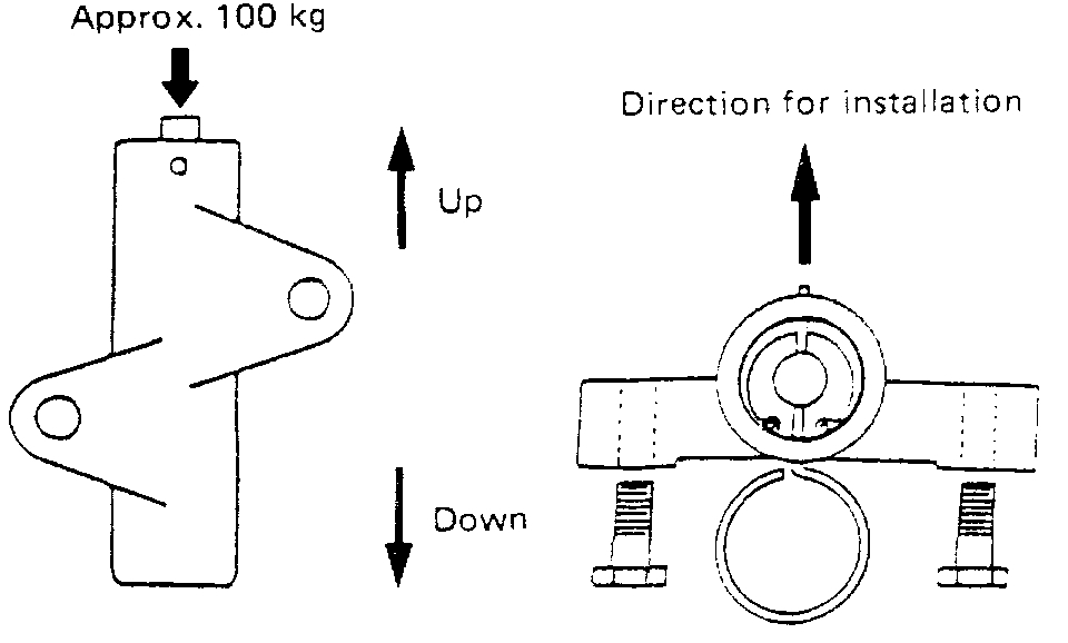
10) Install the pusher while pushing the tension pulley to the belt.
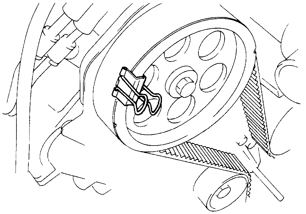
11) Pull out the pin from the pusher.
See picture 11
NOTE:
- When reusing the pusher, press the pusher to retract the rod and insert a pin (1.4 mm piano wire).
See picture 12
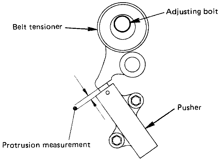
12) Remove double clips from pulleys. Turn the crankshaft pulley clockwise by two turns. Measure the rod protrusion to ensure it is within the standard.
Standard 4-6 mm (0.16-0.24 in)
13) If out of standard, remove pusher, loosen adjusting bolt, and readjust. (Repeat from step 11). Tighten adjusting bolt to the specified torque.
Torque 42 N-m (31 lb-ft)
12. Pusher
- Tighten bolt to the specified torque.
Torque 19 N-m (19 lb-ft)
11. Timing belt cover
- Remove crankshaft pulley that was installed in step 9.
- Tighten bolts to the specified torque.
Torque 17 N-m (12 lb-ft)
10. Oil cooler hose
- Tighten oil cooler hose bracket bolts to the specified torque.
Torque 22 N-m (16 lb-ft)
9. Crankshaft pulley assembly
- Using special tool J-8614-01, hold the crankshaft pulley.
- Tighten center bolt to the specified torque.
Torque 167 N-m (123 lb-ft)
8. Crankshaft pulley; P/S belt
- Tighten fixing bolt to the specified torque.
Torque 9 N-m (78 lb-in)
7. Fan pulley assembly
- Tighten fixing bolt to the specified torque.
Torque 22 N-m (16 lb-ft)
6. Power steering tension pulley
5. Generator drive belt
- Engage and adjust with adjuster.
4. Air Conditioning drive belt
- Engage and adjust with adjuster.
3. Power steering pump drive belt
- Engage and adjust with adjuster.
2. Cooling fan assembly
- Tighten nuts to the specified torque.
Torque 8 N-m (69 lb-in)
1. Radiator upper fan shroud
______________________
Let me know if this is what you needed or if you have other questions.
Take care,
Joe
Images (Click to make bigger)
Thursday, January 24th, 2019 AT 5:26 PM