Hi,
There really isn't a relearn. Here are the directions for removal and replacement of the distributor. The attached pics correlate with the directions.
_________________________________
1997 Chevy Truck K Tahoe 4WD V8-5.7L VIN R
Distributor Removal & Installation
Vehicle Powertrain Management Ignition System Distributor Service and Repair Procedures Distributor Removal & Installation
DISTRIBUTOR REMOVAL & INSTALLATION
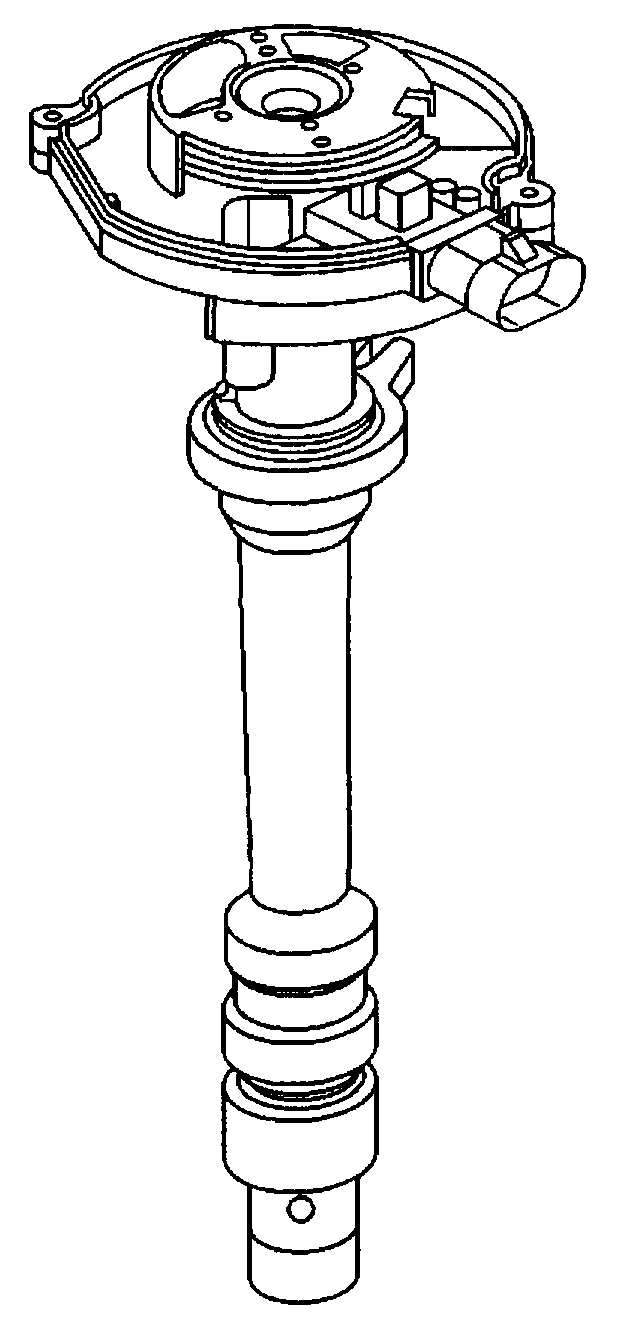
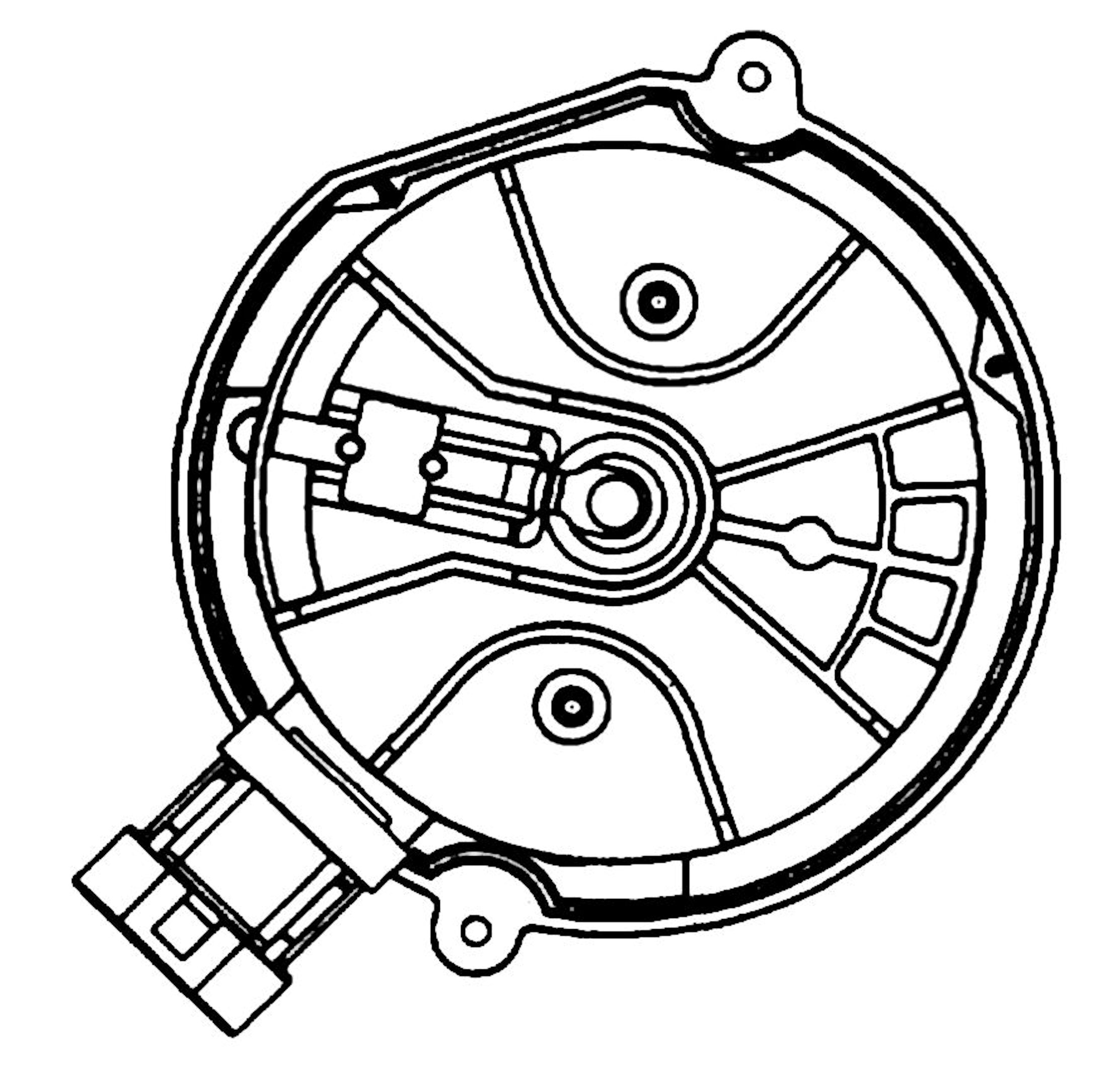
Distributor Installation And Removal (5.0L And 5.7L)
pic 1
Remove or Disconnect
- Make sure the ignition switch is "OFF".
NOTICE: If the distributor is removed from the engine, it can be re-installed using "procedure A" as long as the crankshaft has not rotated from its initial position. If the intake manifold, cylinder head, crankshaft, camshaft, timing sprocket or complete engine was removed or replaced, "procedure B" must be followed to correctly install the distributor. A DTC code may also indicate an incorrectly installed distributor and engine or distributor damage may occur. Procedure B must then be used.
Procedure A
1. Spark plug and coil leads from the distributor cap.
2. Three wire hall effect switch connector from the base of the distributor.
3. Two screws holding the distributor cap to the housing.
4. Distributor cap.
a. Use a grease pencil to note the position of the rotor segment in relation to the distributor housing. Identify the mark with a 1.
b. The distributor housing and intake manifold should also be marked with a grease pencil for proper alignment when reinstalling.
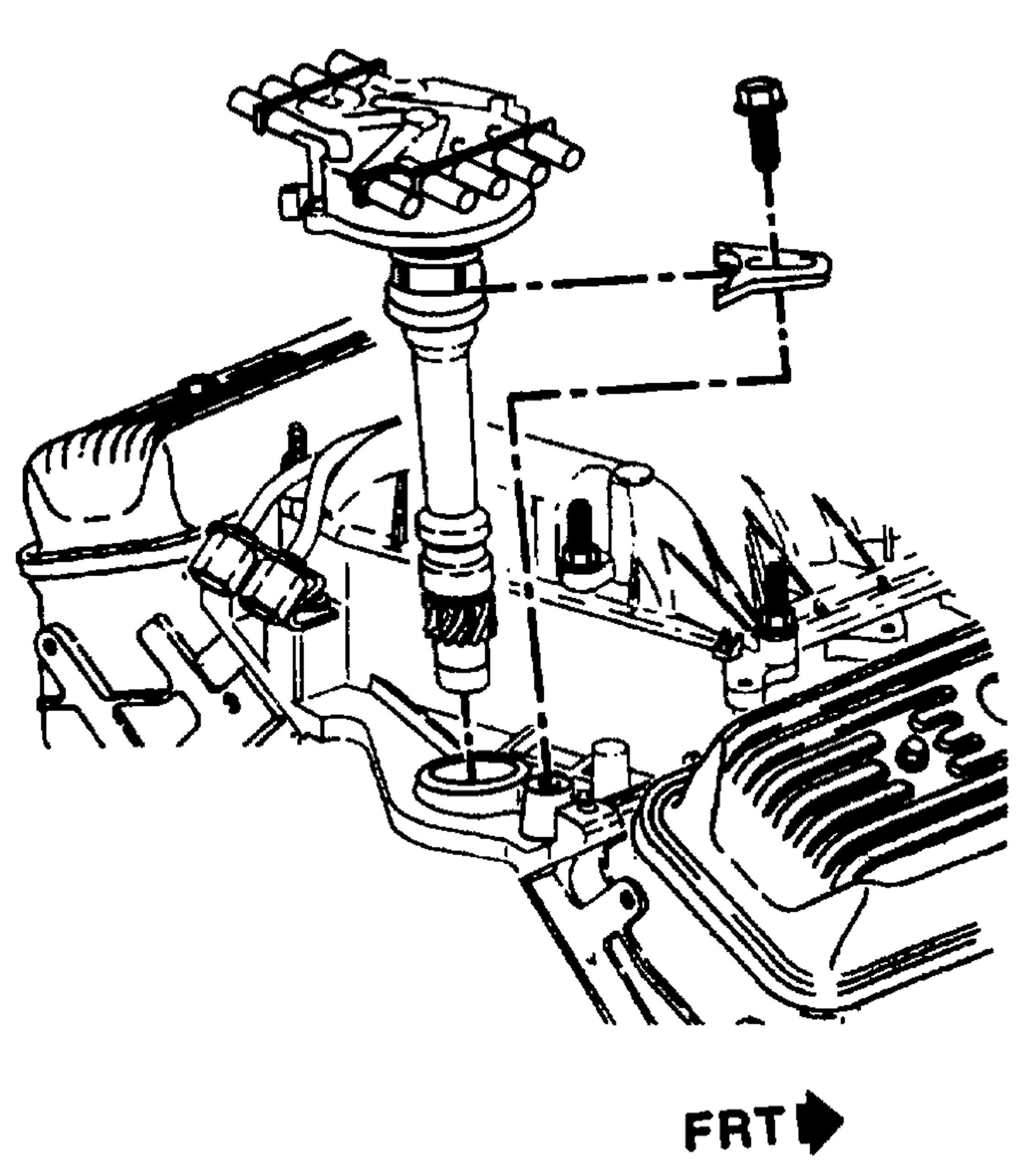
5. Mounting clamp hold down bolt.
6. Distributor.
- As the distributor is being removed from the engine, you will notice the rotor move in a counter-clockwise direction, 42 degrees. This will appear as slightly more than one clock position. Noting the position of the rotor segment, by placing a second mark on the base of the distributor, will aid in achieving proper rotor alignment during distributor installation. Be sure to identify the second mark on the base with the number 2.
Distributor Installation And Removal (5.0L And 5.7L)
pic 2
Rotor Position (5.0L, 5.7L And 7.4L)
pic 3
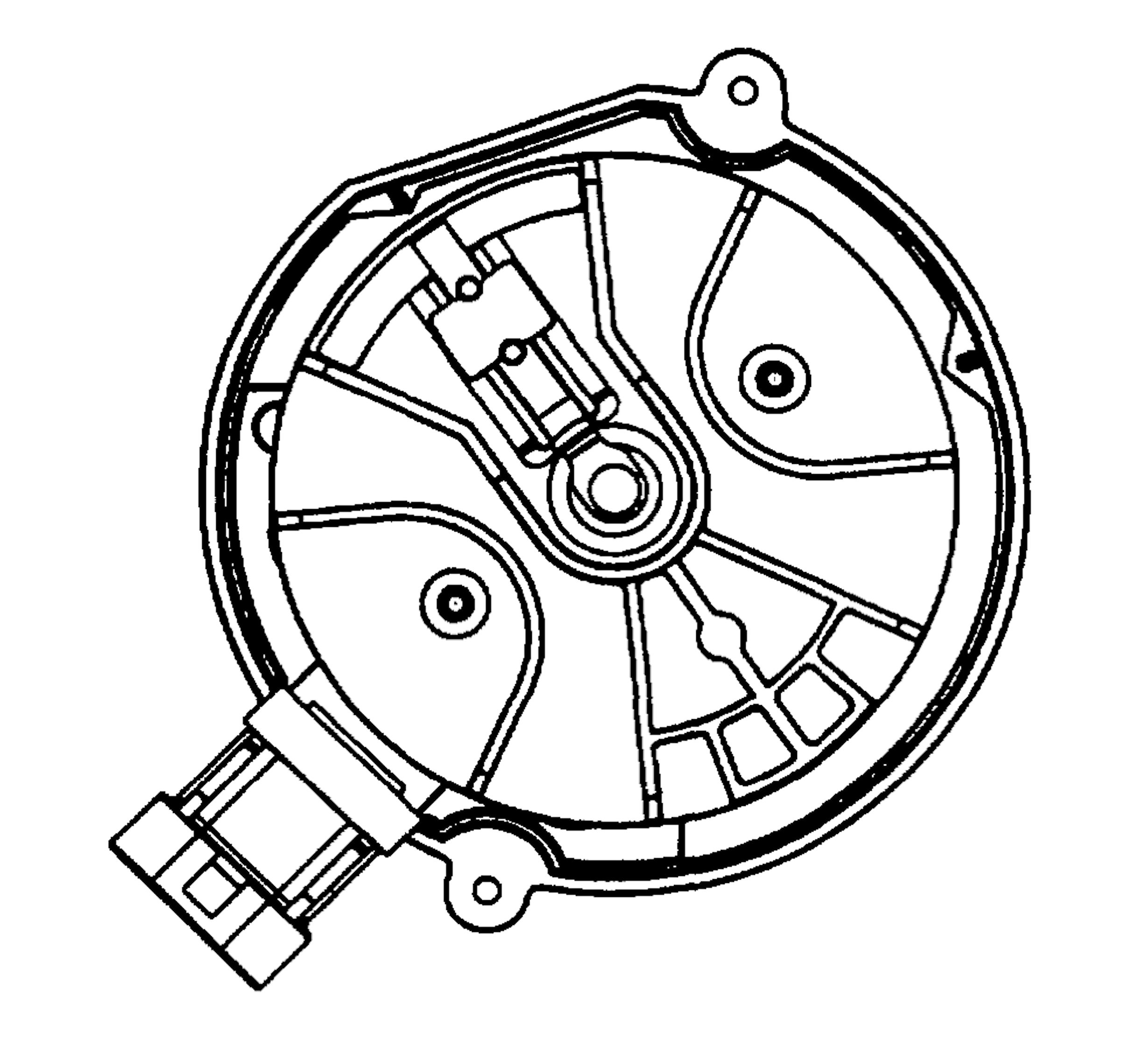
Installed Rotor Position
pic 4
Distributor Alignment Indicator
pic 5
Install or Connect
A. If the original distributor is to be replaced, rather than repaired, remove the new distributor cap. Using a grease pencil, place two marks on the new distributor housing in the same location as the two marks on the original housing.
B. When installing the distributor, align the rotor segment with the number 2 mark on the base of the distributor. Guide the distributor into place, making sure the grease pencil marks on the distributor housing and the intake manifold are in line. As the the distributor is being installed, you will notice the rotor will move in a clockwise direction, 42 degrees. ONCE THE DISTRIBUTOR IS COMPLETELY SEATED, the rotor segment should be aligned with the number 1 mark on the base. If the rotor segment is not aligned with the number 1 mark, the gear teeth of the distributor and camshaft have meshed one or more teeth out of time. To correct this condition, remove the distributor and re-install it following the procedure at step B.
1. Distributor cap and mounting screws. Do not overtighten the screws as the boss may strip.
2. Distributor mounting clamp and tighten to the proper torque.
Tighten
Distributor clamp and bolt to 27 N.m (20 lb. ft.).
Distributor cap screws to 5 N.m (40 lb. in.).
3. Three wire hall effect switch connector to base of the distributor.
4. Spark plug and coil leads to the distributor cap.
- If a check engine light is illuminated after installing the distributor and a DTC P1345 is found, the distributor has been installed incorrectly. You now must refer to procedure B for proper distributor installation.
Procedure B
- Bring the engine up to Top Dead Center (TDC) of cylinder number 1. Make sure it is on the compression stroke.
A. Remove the distributor cap screws and cap to expose the rotor.
Rotor Position (5.0L, 5.7L And 7.4L)
pic 6
Distributor Alignment Indicator
pic 7
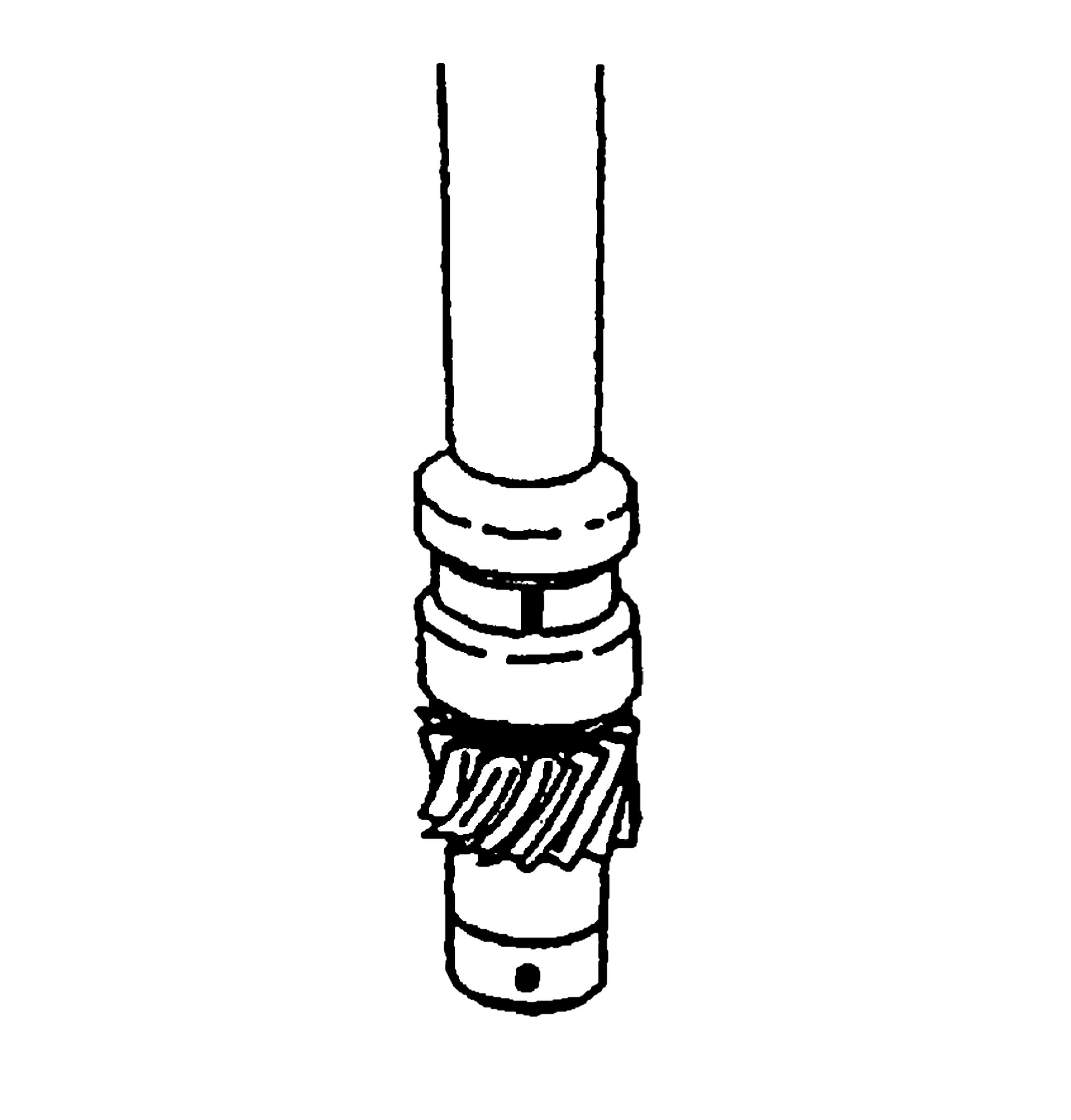
B. Align the pre-drilled indent hole in the distributor driven gear with the white painted alignment line on the lower portion of the shaft housing. The rotor segment should point to the cap hold area.
C. Using a long screw driver, align the oil pumpdrive shaft in the engine in the mating drive tab in the distributor.
D. Guide the distributor into place, making sure the spark plug towers are perpendicular to the center line of the engine.
Installed Rotor Position
pic 8
E. ONCE THE DISTRIBUTOR IS FULLY SEATED, the rotor segment should be aligned with the pointer cast into the distributor base. This pointer will have a "6" or an "8" cast into it, indicating the distributor is to be used in a 6 cylinder or 8 cylinder engine. If the rotor segment does not come within a few degrees of the pointer, the gear mesh between the distributor and camshaft may be off a tooth or more. If this is the case, repeat the procedure again to achieve proper alignment.
Distributor Installation And Removal (5.0L And 5.7L)
pic 9
Rotor Position (5.0L, 5.7L And 7.4L)
pic 10
Installed Rotor Position
pic 11
Distributor Alignment Indicator
pic 12
Install or Connect
1. Cap and mounting screws. Do not overtighten the screws as the boss may strip.
2. Distributor mounting clamp and tighten to proper torque.
Tighten
Distributor clamp and bolt to 27 N.m (20 lb. ft.).
Distributor cap screws to 5 N.m (40 lb. in.).
3. 3 wire hall effect switch connector to base of distributor.
4. Spark plug and coil leads to the distributor cap.
- If a check engine light is illuminated after installing the distributor and a DTC P1345 is found, the distributor has been installed incorrectly.
_________________________________
Let me know if this helps.
Joe
Images (Click to enlarge)
Oct 12, 2020 at 7:08 PM