That's all part of the connector view I posted. Some of the color designations differ between manufacturers, especially from the imports.
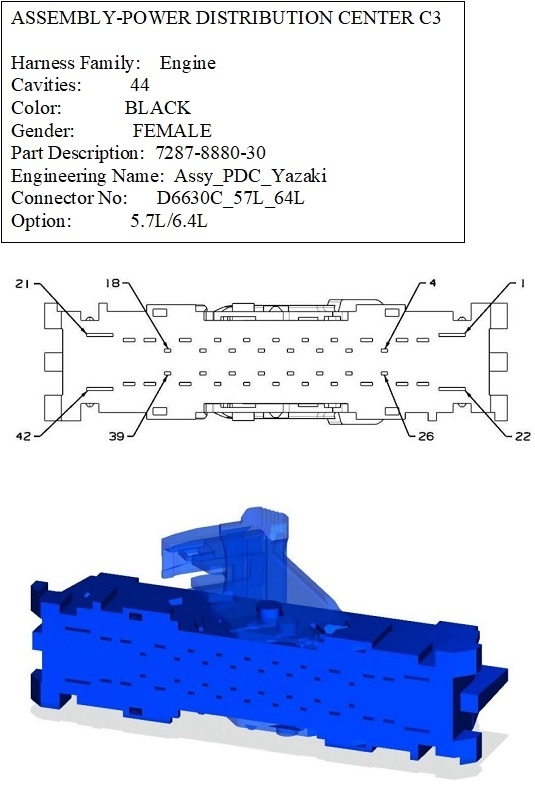
First, hold the connector body with the wires in your hand, away from you, so you're looking at the terminals. The outline shows the various keyways and notches that prevent you from plugging it in turned around, but I often look at the wire colors in the four corners as a faster way of making sure I'm looking at it right. In this case, terminals 22 and 42 are both empty, or not used. Orient the connector so those two openings are down, now, terminal # 1 is at the top right. It takes a little more work to follow them across when they're in a zigzag pattern like they are here. I have to take an extra minute to familiarize myself with each one, and again, it helps when most of the wires are in their correct places so I can double-check myself.
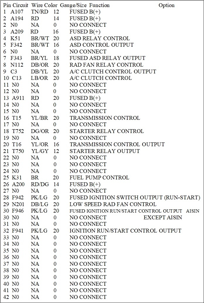
For the wire designations, they don't make sense at first, but they actually do follow a simple pattern. Starting with terminal # 1, for example, it's listed as "A107 12TN/RD". You don't have to memorize the first letter, "A" in this example, but if you do a few, it helps to show when you've accidentally jumped off track somewhere. "A" circuits can be tied back to the battery positive post. "Z" circuits go to ground. Lighting, wipers, speakers, all have their own too.
The "107" is just to show it is different from all the others. Often you'll see the same number in a lot of other places, then that tells you you're in the same circuit without bothering to have to follow it around and waste time figuring that out for yourself.
The next two digits are for the wire's gauge. Sometimes you'll find two wires of the same color, even in the same plug. To tell them apart, you don't have to measure their gauges. You only have to realize that one is fatter than the other. If you ever run into two exactly identical wires, more than likely they originated from the same place, but they go to two different places, such as a left and right tail light.
This is one of two things Chrysler did to make sure you're thoroughly confused. Since at least the 1960s, they used the actual gauge number, like 18 gauge, 14 gauge, etc., but apparently that was too simple. Now they've gone to a metric size that I think is in millimeters. I haven't become comfortable with that yet, but it explains why you will see some numbers that don't follow what I described. In fact, the diagram below is from our aftermarket online service manuals. I tried to copy all of the diagrams for my 2014 Ram, and just as I was getting close to half done, they dropped Chrysler's diagrams and went to just their own. Luckily they hadn't done that yet to the 2013 models, so I finished up with those, since they're the same.
To continue, the last letters designate the wire color. The first two letters indicate the main color, such as "brown", (BR), "red", (RD), etc. The second pair of letters indicates the color of the stripe, or "tracer" on that wire, so "TN/RD" is a tan wire with a red tracer. "BK" is black, and "BL" is blue. Let me know if you run into a color you can't figure out. Every once in a while you'll run into two letters with an asterix, like L234 18RD*. That means it's a red 18 gauge wire, but the tracer can vary depending on the wires that were supplied to different assembly plants. Sometimes they'll show two wires side by side inside a pair of brackets. There will be a note then to explain why. Most often you'll follow one wire if you have an automatic transmission, and the other for a manual transmission. This is common too when one diagram covers 2 and 4-wheel-drive models, and when it covers different engine sizes.
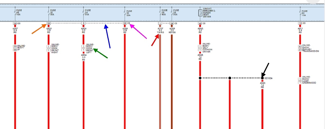
Some information is lost when you go to these aftermarket diagrams, but they make some things easier. The second example of this is they put entire circuits on one diagram here. I only posted a small, expanded section of one diagram below so I could point some things out. When you use a diagram right from Chrysler, the confusing part is it will cover many "sheets", and where a wire comes to an unexpected end, it will say which sheet number it is continued on. That's because when they draw these up, they may have hundreds of sheets laid out, but they don't know which page number each sheet will end up on when it goes to the printer. Page numbers might not even be shown in the paper manuals. Sheet numbers are on the top or bottom corners of the pages
Now, if you look at my nifty arrows in the diagram below, this is the aftermarket version, but it follows many of the same designations. This is a small section of the Integrated Power Module, (IPM), you're working on. The red arrow is pointing to the wire I used for my example. It's for terminal # 1 in connector C3. Just to the right of it they show terminal # 26. The dashed line, (blue arrow), between pins 1 and 26 show that they're both in the same connector, C3 in this case.
The orange arrow is pointing to the terminal number, the pink arrow is pointing to the connector number, and the dashed line, (blue arrow) shows that terminals 5, 26, and 28 are all in connector C5.
The green arrow is pointing to a connector that isn't part of any module. They call them "inline" connectors. Those just make it easy to connect various harnesses or assemblies while the vehicle is being assembled. Those make nice test points when other things are hard to get to or find.
The black arrow is pointing to a splice. Here they just show the individual wires and you have to know they're all tied together. On Chrysler's diagrams, they actually show them all together with a single black dot for the splice. Original diagrams also have pages that show the locations of splices and inline connectors. Splices are good places to look for corroded and intermittent connections on older vehicles.
See how far you get now, then let me know where you get stuck.
Sep 13, 2025 at 5:26 PM