Hi j641350,
Thank you for the donation.
Here are the basic diagnostics when engine can be cranked and not starting. Go through them and if you require additional assistance, just post replay and I will get back to you.
NO START - ENGINE CRANKS OKAY (3.8L WITH C( 3 )I)
NOTE: Before performing following tests, check battery condition, engine cranking speed and for adequate fuel in tank.
General Inspection
1 . Ensure proper starting procedure is being used. Visually check vacuum hoses for splits, kinks and proper connections, as shown on Vehicle Emission Control Information label. Check ignition wires for cracking, hardness and proper connections at both coil pack and spark plugs.
2 . Remove spark plugs. Check and replace as necessary. In very cold temperatures, ensure oil is proper viscosity and not contaminated with gasoline.
Ignition System (VIN K, L & 1)
1 . Ensure TP sensor scan is less than 2.5 volts. If not, see Code P0123 chart. Scan PASS -Key (R) II. Display should show ENABLED. If not, diagnose theft deterrent system. Check for stored trouble codes. If engine has not been started for at least 8 hours, MAT sensor scan temperature should be close to ECT sensor scan temperature.
2 . Disconnect tachometer wire (if equipped). A shorted tachometer or tachometer circuit will not allow vehicle to start. Disconnect cam sensor and attempt to start engine. If engine starts, see Code P0341 chart. If engine does not start, go to next step.
3 . Reconnect cam sensor connector. Compare scanned ECT sensor temperature with actual coolant temperature. If scanned value are not close, replace coolant sensor. Depress accelerator pedal about 25 percent throttle angle. Attempt to start engine. If engine does not start, go to next step. If engine starts, check IAC counts on scan tester. Check for blocked IAC passages.
4 . Disconnect all injector connectors and install injector test light on each injector harness connector. All lights should be off and should blink as engine is cranked. If any injector lights are on, go to step 8). If lights do not blink at all while cranking, go to step 9). If all lights are off and blink as engine is cranked, go to next step.
5 . Check for adequate spark using Spark Tester (ST- 125). Check for spark on plug wires No. 1, 3 and 5 (one at a time). Leave matching plug wire connected while checking for spark. If spark jumped across tester on all plug wires, check for fouled spark plugs or for fuel system as cause of no start. If spark did not jump tester or was not present on any plug wire, check poor ignition module connection or faulty ignition module.
6 . If spark did not jump tester on all plug wires, ensure spark plug wire resistance is less than 30,000 ohms. Ensure ignition coil secondary resistance is 5000 -6500 ohms at room temperature. Replace as necessary. If wires and coils are okay, remove coil that did not fire. Verify coil primary resistance of .5 - .9 ohm. Replace coil if necessary. If coil is okay, connect test light across ignition module terminals of problem coil.
7 . Crank engine. If test light flashes, check for poor coil -to-module connections. If connections are okay, replace faulty coil. If test light does not flash, replace ignition module.
8 . Turn ignition off. Disconnect PCM Red connector. Turn ignition on. If all lights are off now, replace PCM. If any lights are still on, repair short to ground in that injector drive circuit.
9 . Check ignition module power supply (F/P -IGN fuse and circuit). Repair as necessary. Disconnect fuel injector connector. Turn ignition on. With a test light connected to ground, check for battery voltage on Pink/Black wire of injector harness. If test light is on, go to next step. If test light is off, check INJ fuse. If fuse is blown, repair short to ground and replace fuse. If fuse is okay, check power supply to fuse and circuit between fuse and the injector harness connector.
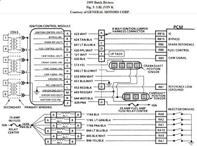
10 . Turn ignition off. Disconnect ignition module connector. Turn ignition on. Install injector test light to any injector harness connector. Connect test light to battery voltage, and repeatedly touch terminal "D" of ignition module harness connector. See Fig. 3 . Injector test light should flash each time test light is touched to terminal "D". If injector test light flashes, go to step 12).
11 . If injector test light does not flash, check injector drive circuit between PCM and injector harness connector for open or short to voltage. Repair as necessary. If injector drive circuit is okay, check for open, short to ground or short to voltage on fuel control circuit No. 430 (Purple/White wire). If circuit is okay, problem is faulty connection at PCM fuel control terminal or faulty PCM.
12 . Turn ignition off. Using proper jumper adapter from Adaptor Kit(J- 35616), connect a fused jumper wire between ignition module harness connector terminal "N" and battery voltage. Connect a second jumper between ignition module harness connector terminals "M" and ground. Connect DVOM between ignition module harness connector terminal "H" and battery voltage. Observe voltmeter while cranking engine. Voltmeter should read about 1 -3 volts.
13 . If voltage is high, check circuit No. 646 for open or short to ground. If circuit No. 646 is okay, replace faulty crank sensor. If voltage is low, check circuit No. 646 for an open or short to voltage, circuit No. 645 for an open and circuit No. 644 for an open or short to ground. If all circuits are okay, replace faulty crank sensor.
14 . If voltage is about 1 -3 volts, move DVOM lead from terminal "H" to terminal "G". Crank engine and once again monitor voltage. Voltmeter should read about 5 - 7 volts. If voltage is correct, go to next step. If voltage is less than 5 - 7 volts, check for open or short to voltage in circuit No. 643. If voltage is greater than 5 - 7 volts, check for a short to ground on circuit No. 643. If no problem is found, crank sensor is faulty.
15 . If voltage is close to 5 -7 volts, turn ignition on. Probe ignition module harness connector terminals "P" with a DVOM connected to ground. If battery voltage is not present, repair open in ignition module power supply circuit. If battery voltage is present, problem is poor ignition module connections or faulty ignition module.
Fuel System (VIN K & 1)
1 . Before checking fuel system for a no- start condition, check ignition for adequate spark. Check for proper fuel pump pressure and capacity.
2 . Turn ignition off. Install fuel pressure gauge. Using a fused jumper wire connected to battery voltage, jumper fuel pump test terminal. Turn ignition on. Listen for fuel pump operation and note fuel pressure gauge reading.
3 . If fuel pump operates and fuel pressure is okay, go to next step. If fuel pump does not operate, go to step 8). If fuel pump operates, but fuel pressure is not present, go to BASIC FUEL SYSTEM CHECKS.
4 . Remove jumper wire. Remove fuel pump relay. Connect test light between fuel pump relay connector Red wire and Black/White wire terminals. If test light illuminates, go to next step. If test light does not illuminate, connect test light between ground and relay connector Red wire terminal. If test light illuminates, check for open in Black/White wire. If test light does not illuminate, check for open in Orange, Pink or Red wire.
5 . Turn ignition off. Connect test light between relay connector Dark Green/White wire and Black/White wire. Turn ignition on. If test light illuminates for about 2 seconds, go to next step. If test light does not illuminate, check for poor relay connections. If connections are okay, replace fuel pump relay.
6 . Turn ignition off. Connect test light to ground. Backprobe PCM connector Dark Green/White terminal (fuel pump driver circuit). Turn ignition on. If test light illuminates for about 2 seconds, check for open in Dark Green/White wire. If test light does not
illuminate, go to next step.
7 . Disconnect PCM connector. Using test light connected to battery voltage, probe PCM connector Dark Green/White wire terminal. If test light illuminates, check Dark Green/White wire for short to ground. If test light does not illuminate, check for faulty PCM connector or faulty PCM.
8 . Turn ignition off. Remove fuel pump relay. Using a fused jumper wire, jumper relay connector Gray wire and Red wire terminals. Turn ignition on. Fuel pressure gauge should indicate fuel pressure. If fuel pressure is present, check for poor relay connection, open in Red wire to fuel pump test terminal or faulty fuel pump relay. If fuel pressure is not present,
go to next step.
9 . Turn ignition off. Raise and support vehicle. Disconnect fuel pump connector at fuel pump. Connect test light between fuel pump connector terminals. Turn ignition on. If test light illuminates, replace fuel pump. If test light does not illuminate, check for open in Gray or Black wire fuel pump.
Oct 17, 2009 at 11:28 PM
