Lower Control Arm Replacement
Tools Required
J 41820 Ball Joint/Stud Separator
Removal Procedure
Notice: Use only the recommended tools for separating the ball joint from the knuckle. Do NOT hammer or pry the ball joint from the knuckle. Failure to use the recommended tools may cause damage to the ball joint and seal.
Important: Use the ignition key in order to unlock the steering column.
Turn the steering wheel in order to move the front of the applicable wheel to the outboard most position.
Important: Use ONLY a frame-contact type vehicle lift or a floor jack at the recommended lift points. Do NOT use a suspension-contact type vehicle lift. Do NOT lift the vehicle by the lower control arms.
Raise and support the vehicle. Refer to Lifting and Jacking the Vehicle .
Remove the tire and wheel. Refer to Tire and Wheel Removal and Installation .
If applicable, disconnect the ABS wheel speed sensor connector.
If applicable, disconnect the ABS wheel speed sensor jumper harness from the harness retainer clips.
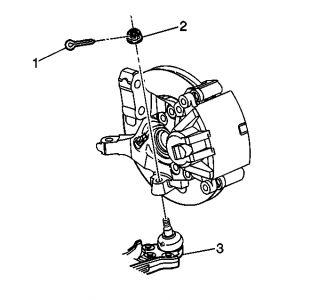
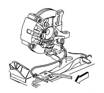
Remove the cotter pin (1) from the ball stud (3).
Loosen the ball stud nut (2).
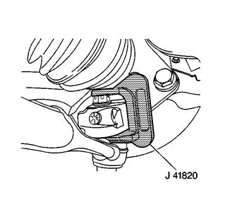
Install the J 41820 over the ball stud and lower control arm as shown.
Rotate the ball stud nut counterclockwise in order to separate the ball stud from the steering knuckle.
Remove the J 41820 .
Remove the ball stud nut.
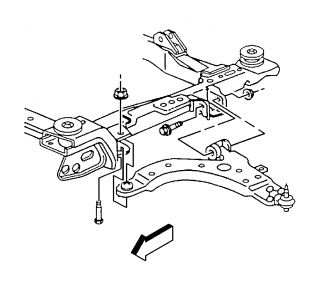
Remove the lower control arm bolts and nuts.
Remove the lower control arm.
Installation Procedure
Install the lower control arm.
Install the control arm bolts and nuts. Do not tighten at this time.
Important: Align the ball stud cotter pin hole parallel to the knuckle in order to ease the cotter pin installation.
Install the ball stud to the knuckle.
Notice: Refer to Fastener Notice in Cautions and Notices.
Install the ball stud castle nut.
Tighten
Tighten the nut to 20 N·m plus 120 degrees (15 lb ft plus 120 degrees).
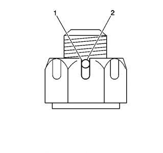
Important: Do NOT loosen the ball stud nut in order to align the ball stud nut slots to the ball stud cotter pin hole.
If necessary, tighten the ball stud castle nut in order to align the ball stud castle nut slot (1) to the ball stud cotter pin hole (2) as shown.
Important: If applicable, ensure that the cotter pin ends do NOT contact the ABS wheel speed sensor, the ABS sensor connector or the drive axle.
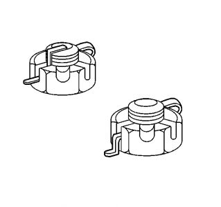
Install a NEW cotter pin and bend the ends as shown in either example.
If applicable, connect the ABS wheel speed sensor jumper harness to the harness retainer clips.
If applicable, connect the ABS wheel speed sensor connector.
Important: This is a prevailing torque type fastener. This fastener may be reused ONLY if:
• The fastener and its counterpart are clean and free from rust.
• The fastener develops 3 N·m (27 lb in) of torque against its counterpart prior to the fastener seating.
If the fastener does not meet these criteria, REPLACE the fastener.
Install the lower control arm nuts.
Tighten
Tighten the lower control arm nuts to 125 N·m (92 lb ft).
Install the tire and wheel. Refer to Tire and Wheel Removal and Installation .
Lower the vehicle.
Jan 12, 2008 at 2:08 PM