Welcome to 2CarPros.
The rear brake drums are not held on with a bolt. The wheel studs which hold the wheel to the axle hole the drum in place once the wheel is attached.
Here is a link that shows in general replacement of the rear brake shoes and drum. Take a look through it.
https://www.2carpros.com/articles/how-to-replace-rear-brake-shoes-and-drums
Here are the directions specific to your vehicle. The attached pictures correlate with these directions.
_______________________________________---
Removal
1. Raise and support rear of vehicle, then remove wheel and tire assembly.
2. Remove brake drum. If brake drum cannot be remove easily, insert a suitable screwdriver through hole in backing plate, then push automatic adjuster lever away from adjuster and back of adjustment tension.
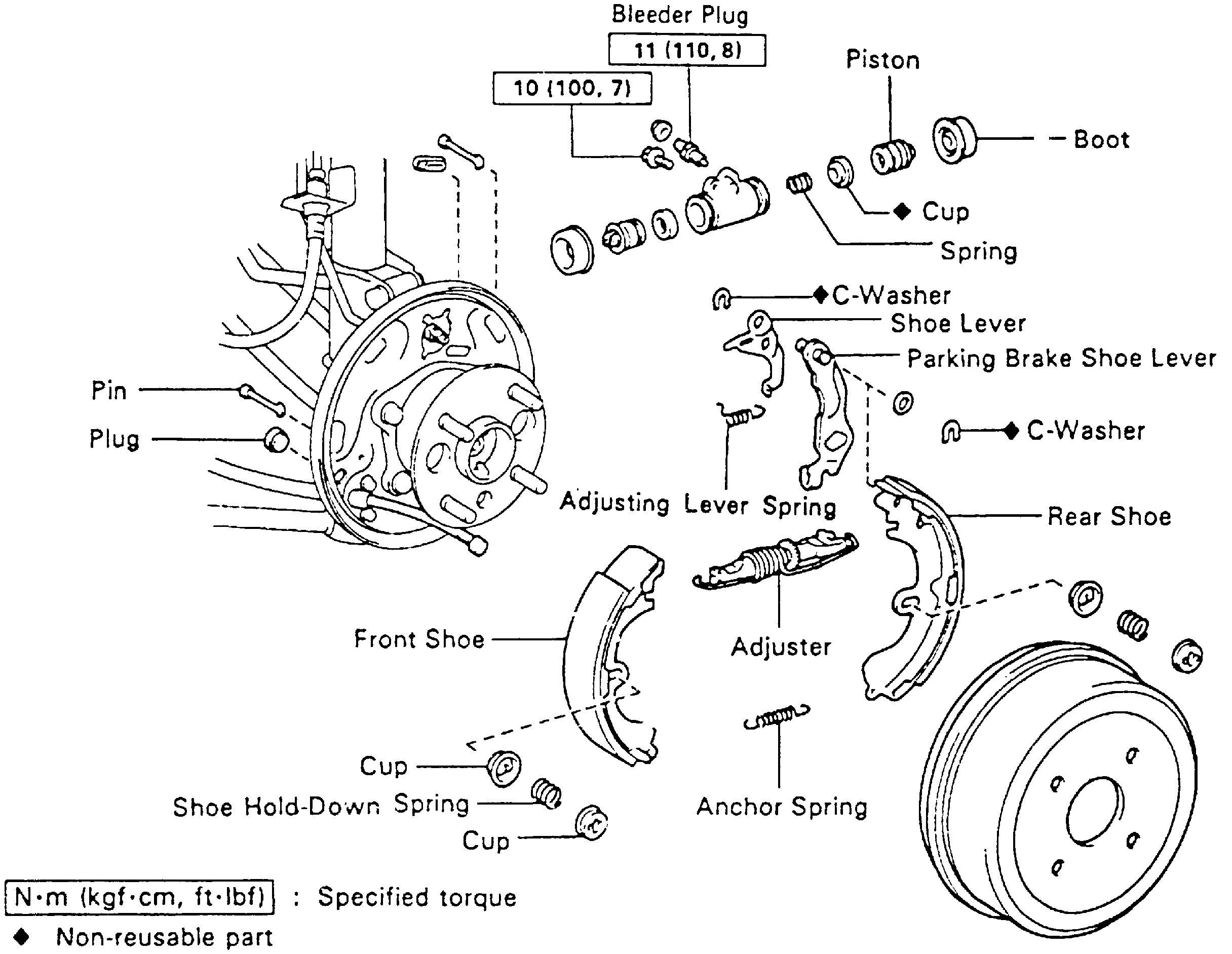
3. Disconnect return spring, using a suitable tool, then remove front shoe hold-down spring, retainers and pin.
4. Disconnect anchor spring, then remove front brake shoe and anchor spring, Fig. 10.
Fig. 10 Exploded View Of Type 6 Drum Brake Assembly.
picture 1
5. Remove rear shoe hold-down spring, retainers and pin, using suitable a tool, then disconnect parking brake cable from anchor plate.
6. Disconnect parking brake cable from lever, then remove rear shoe with strut.
7. Remove adjusting lever spring, strut and return spring from rear shoe.
8. Remove C-washer, then the shims, parking brake lever and automatic adjusting lever from rear shoe.
9. Position a suitable container to catch fluid, then disconnect brake line.
10. Remove two attaching bolts, then the wheel cylinder.
11. Remove two boots, two pistons, two piston cups and spring from wheel cylinder.
Inspection
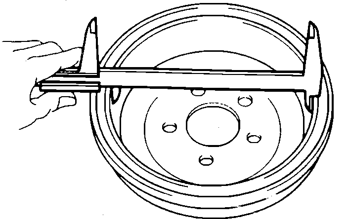
1. Measure brake drum inside diameter. Inside diameter should be 7.87 inches, Fig. 2.
Fig. 3 Measuring Brake Drum Inside Diameter
picture 2
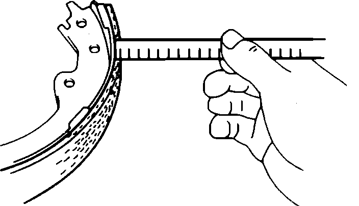
2. Measure brake shoe lining thickness, Fig. 3. Minimum thickness should be .04 inch.
Fig. 4 Measuring Brake Shoe Lining Thickness
picture 3
3. Inspect brake lining and drum for proper contact and replace drum or shoes as necessary.
4. Inspect wheel cylinder for corrosion or damage.
5. Inspect backing plate for wear or damage.
6. Inspect bellcrank components for bending, wear or damage.
7. Apply a suitable lubricant to backing plate contact areas.
Installation
1. Apply a suitable lubricant to pistons and cups, then install spring and two piston cups into wheel cylinder. Apply a suitable lubricant to inside of boots, then insert them into cylinder, Fig. 10.
Fig. 10 Exploded View Of Type 6 Drum Brake Assembly.
picture 4
2. Install wheel cylinder onto backing plate, then insert attaching bolts and torque to 7 ft. lbs.
3. Connect brake tube to wheel cylinder, then torque nut to 11 ft. lbs.
4. Apply a suitable lubricant to adjuster bolt contact points, then install levers, shim and new C-washer.
5. Measure clearance between shoe and lever. Clearance should be .014 inch. If clearance is not as specified, select a suitable shim to bring clearance to specified value.
6. Place strut and return spring on rear shoe, then install adjusting lever spring.
7. Connect parking brake cable to lever, then insert cable through notch in anchor plate.
8. Position one end of rear shoe in wheel cylinder and the other end in anchor plate.
9. Install rear shoe pin and hold-down spring and retainers.
10. Insert anchor spring between front and rear shoes, then position end of front shoe in wheel cylinder with strut in place.
11. Install front shoe hold-down spring, retainers and pin.
12. Install return spring.
13. Ensure adjusting bolt rotates while pulling parking brake upward. If bolt does not turn, check installation of rear brakes.
14. Adjust strut to its shortest possible length, then install drum.
15. Pull parking brake lever fully upward, then repeat step several times.
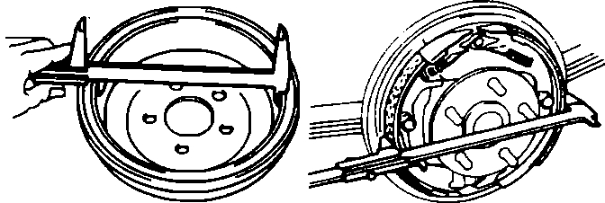
Fig. 5 Measuring Clearance Between Shoes & Drum
picture 5
16. Remove drum, then check for proper clearance, Fig. 4. Clearance should be .024 inch. If clearance is not as specified, check parking brake system.
17. Install brake drum, then bleed and refill brake system.
18. Install wheel and tire assembly, then lower vehicle.
_________________________________
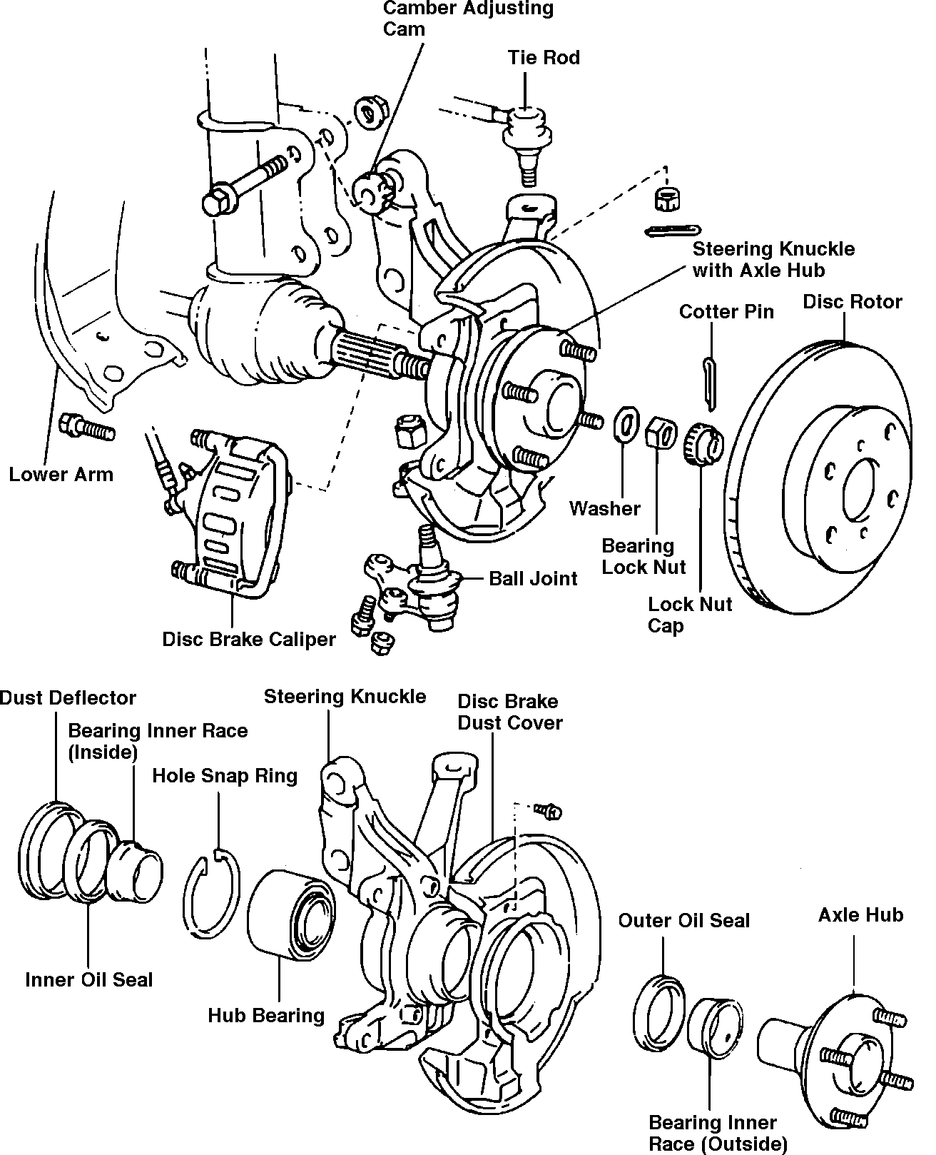
The last pic I attached shows the front brake and hub assembly. There is a bolt that holds the axle in the hub. Is that what you are referring to?
Let me know.
Joe
Images (Click to enlarge)
Mar 29, 2021 at 11:25 AM