1995 BMW 525i (E34) L6-2494cc 2.5L DOHC (M50 TU)
Vehicle Level Engine, Cooling and Exhaust Engine Cylinder Head Assembly Service and Repair Remove
Remove
CYLINDER HEAD REMOVAL
Removing Vanos Control Unit
Unscrew oil pipe at VANOS control unit.
Installation Note : Check seals, replacing them is necessary. Torque to 50 ±5 Nm (37 ±3 lb ft) .
Unscrew suspension eye.
Installation Note : Check for ground strap (1).
Unscrew pulse sender.
Remove wiring duct for pulse sender.
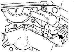
Remove Thermostat Housing Cover If applicable, unscrew thermostat housing for other work on cylinder head later.
Installation Note : Sealing surfaces must be clean and without oil.
Check rubber profile gasket, replacing it if necessary.
Installation Note : Check installed direction. Vent or arrow faces up. Replace seal.
Remove Cylinder Head Cover
If applicable, pull plugs off of ignition coils.
Unscrew nuts.
Remove ignition coils.
Installation Note : Check for ground strap of ignition coils at cylinder 3 and 6.
Unscrew cylinder head cover.
NOTE : Cylinder head cover is separated from the cylinder head as far as transmission of oscillation is concerned by employing rubber mounts and gaskets.
Check arrangement of cover installation. 1 Cover nut
2 Washer
3 Rubber mount
Installation Note : Check cover gasket, replacing it if necessary. Place outer and inner cover gaskets on cylinder head in advance.
Installation Note : Check for correct seating of gasket on back of the cylinder head when mounting the cylinder head cover.
Installation Note : Install and align cover.
Screw on cover nuts, but do not tighten them.
Tighten cover nuts diagonally from inside to outside. Torque bolts to: 6 mm 10 Nm (7 ft lb) 7 mm 15 Nm (11 ft lb) .
Take off plastic cover.
Lift out lock and remove plastic cover for the intake camshaft.
Turn engine in its direction of rotation until the peaks of cams on intake and exhaust camshafts for cylinder no. 1 point to each other.
Hold crankshaft in TDC using Special Tool 11 2 300.
CAUTION : Remove special tool before operating the engine.
Hold camshafts using Special Tool 11 3 240.
Screw plugs out of control unit.
Unscrew bolts of sprocket on the exhaust camshaft.
Press down on upper chain tensioner and lock using Special Tool 11 3 290.
Unscrew nuts.
Remove VANOS control unit.
Installation Note : Check for dowel sleeves (1). Apply 3 Bond 1209** liquid sealing compound at the corners of the joint between the cylinder head and VANOS control unit. Replace gasket.
Unscrew nuts of intake camshaft.
Remove thrust washer.
Remove sprockets together with chain.
NOTE : If applicable, for work on the cylinder head later.
unscrew thrust washer bolts.
Remove thrust washer.
Remove sender gear.
Installation Note : Tightening torque.
Sprocket To Camshaft Flange
7mm [1]
Step #1 5 Nm (3.5 ft lb)
Step #2 22 Nm (16 ft lb) .
6mm [1] 10 Nm (7 ft lb) .
Splined Shaft To Intake Camshaft
14X1.5 [1]
Step #1 40 Nm (30 ft lb)
Step #2 Torque Angle 60° .
[1] Screw size.
Unscrew secondary tensioner.
Unscrew chain guide.
Unscrew chain tensioner.
Caution : Spring pressure.
Installation Note : Align groove in piston perpendicular to the tensioning rail. Replace gasket.
Arrangement of Parts:
1 - Sleeve
2 - Spring
3 - Piston
Press upper chain tensioner down and arrest by inserting Special Tool 11 3 290.
Unscrew sprockets.
Lift both sprockets off complete with chain.
Unscrew console for upper chain tensioner.
Lift sprocket off together with chain.
CAUTION : Prevent chain from slipping down with a piece of wire.
Unscrewing Cylinder Head
Unscrew timing case cover from cylinder head.
Unscrew cylinder head bolts in several steps from outside to inside using Special Tool 11 2 250.
Lift cylinder head off.
NOTE : Some of the washers are locked in the standard cylinder heads to prevent them from being lost.
Sep 20, 2010 at 8:49 PM