This is the world's first "AC" charging system. The original version goes back to 1960 when Chrysler copyrighted the term "alternator". We should be able to figure this out with a few voltage measurements.
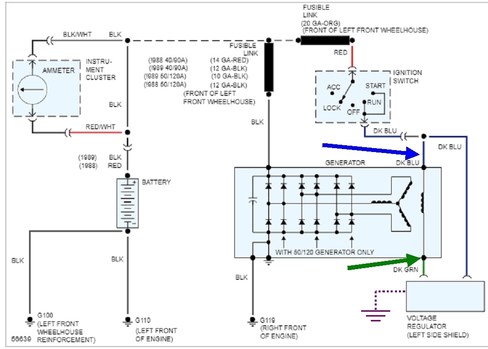
Specifically, with the engine running, measure the voltage on the two smaller wires plugged onto the back of the alternator. You should find full system voltage on the dark blue wire. The control wire is the dark green wire. Expect to find between roughly 4 to 11 volts. The lower the voltage, the harder the alternator is working. If you find 0 volts, the dark green wire is likely shorted to ground, or the voltage regulator is shorted internally. That is not common. If the regulator is shorted, the alternator will stop charging when the plug to the regulator is disconnected. If it's still charging wide-open, the dark green wire is grounded.
That can be verified by measuring its resistance to ground.
If you find low voltage on the dark green wire, but not 0 volts, the voltage regulator is trying too hard to ground that wire. Unplug the regulator's plug, then in that plug, measure for voltage on the terminal corresponding to the dark blue wire. That circuit serves two purposes. First, it supplies the power to run the regulator's circuitry, and second, it is the circuit where it senses system voltage. If there's excessive resistance in that wire or terminal, the regulator will see voltage that is too low. In response, it will become a lower resistance so more current flows through the alternator's field circuit. That makes a stronger electromagnet so the alternator develops higher output voltage and current.
Testing for high resistance in a wire can be very misleading and confusing because for it to cause voltage that's too low, current has to be flowing through it. Digital voltmeters don't draw enough current to make that resistance show up. For this type of problem, an old-style, inexpensive test light with an incandescent bulb inside is a much better choice. They require current flow to operate. The problem here is you don't get an exact voltage reading.
A trick I use quite often is to test first with the digital voltmeter, get the voltage reading, then with it still connected, test with the test light at the same time. If there's excessive resistance in that dark blue wire, you'll see full battery voltage of near 12.6 volts, then it will drop a noticeable amount when the test light is added.
If you haven't found the defect by now, there's one more rather rare and elusive cause to look for. That's the ground for the voltage regulator. It's not shown in this diagram, so I added it in purple at the lower right of the page. The regulator has to be bolted solidly to the firewall, and the housing and the body sheet metal have to be paint and rust-free to make a good connection.
During normal operation, the voltage regulator wants to see between 13.75 and 14.75 volts on the dark blue wire. That is in reference to ground. If there is some rust on the body where the regulator is bolted, current flowing through that rust will "drop" some voltage across it. When the system is charging wide-open, current flow through the alternator's field circuit will be three amps. Those three amps continue on through the dark green wire, through the regulator's circuitry, its housing, that spot of rust, then through the sheet metal and back to the battery. Three amps through that rust can easily drop more than 3 to 5 volts across it. Between the housing and the dark blue wire, that leaves around 8 to 10 volts to be "seen" by the regulator. It incorrectly thinks system voltage is too low, so it keeps on trying to make the alternator work harder. Even though you see 19 volts at the battery, the regulator is only seeing perhaps 14 volts with the other five volts being dropped across the rust.
Testing the ground is pretty easy. Place one voltmeter probe on a good, paint-free point on the body such as a clean bolt head, or even right to the battery's negative post. Touch the other probe right to a paint-free point on the voltage regulator's housing. Those are supposed to be the same points in the circuit, so you're supposed to find 0.00 volts. If there's anything other than a perfect connection, you will find some voltage. That proves the physical connection has to be cleaned up or tightened.
For the benefit of others researching this topic, here's links to some articles that may be helpful:
https://www.2carpros.com/articles/how-to-use-a-voltmeter
https://www.2carpros.com/articles/how-to-use-a-test-light-circuit-tester
Jan 31, 2022 at 4:21 PM