You do have the common regulator used for this modification. I did the same thing on my skid steer. While the setup will get the job done, there are some technical problems with it. This was the first electronic voltage regulator, first used by Chrysler on 1970 models. They have a really long list of "firsts" that truly benefitted car owners.
The first problem is this regulator has temperature compensation built in, but that's all. Charging the battery is a chemical process, and those slow down in colder temperatures. This regulator will bump up charging voltage a little in cold weather.
Other manufacturers like to put the regulator inside the generator, making it an easy-to-replace package deal. You have to buy both parts when one of them fails. With Chrysler's design, the alternator remains a stand-alone part, so that's all you replace when it fails. By putting the voltage regulator inside the Engie Computer, it can respond to everything the computer knows. Specifically, it knows battery temperature, engine coolant temperature, engine load, engine speed, and a number of "anticipation" controls. That means it knows for example, when the computer is about to cycle on the AC compressor or the rear window defogger. Both require extra current, so instead of that sudden current increase causing a drop in voltage, and dimming lights, it ramps up alternator output just before those higher loads begin. The external regulator has no way of knowing that. It can only respond after the loads occur and system voltage has dropped.
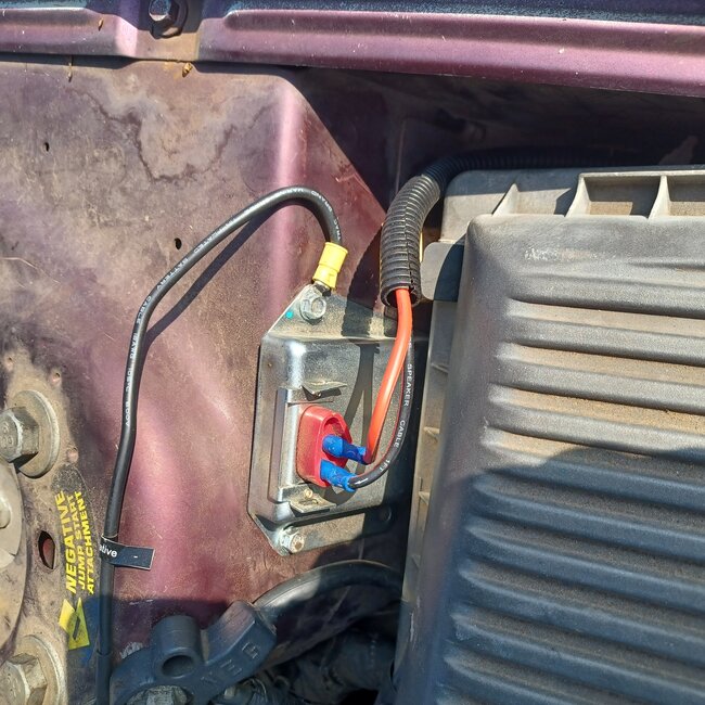
The second thing to be aware of, while likely not the problem here, is this regulator has a third, very important wire. That is the ground made through its metal housing. Relying on the bolt threads is not the best idea. Instead, consider scratching a clean surface through the paint to get the best possible connection. To check the connection, use a digital voltmeter on the lowest DC volts scale, then measure the voltage drop between a clean spot on the housing and the battery's negative post. Since mechanical connections are involved, there will be some slight voltage drop, but it should be in the order of millivolts. I'd expect to see less than perhaps 10 to 20 millivolts. If you find more than that experiment with additional ground wires between the engine and body sheet metal, and between the body sheet metal and the battery's negative cable. That will be the smaller cable of the two in the negative cable clamp.
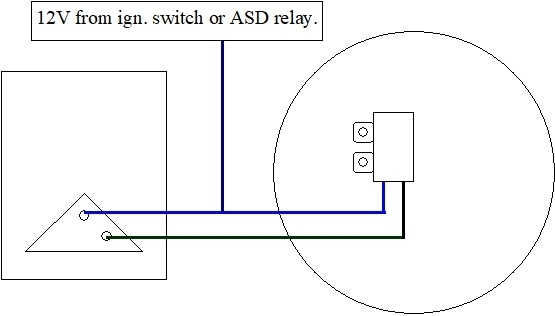
The next concern has to do where you're getting the 12 volts to run the regulator. The Engine Computer usually has four 12-volt supplies. One is constant to maintain learned fuel trim numbers, sensor personalities, and any diagnostic fault code data. A second supply from the ignition switch turns the computer on. There may be a third supply that gets switched onto one of the outputs to turn on the automatic shutdown, (ASD), relay. That relay feeds 12 volts to the ignition coil(s), injectors, fuel pump or pump relay, oxygen sensor heaters, and it is the fourth 12-volt supply going back to the computer. That is the 12 volts the computer looks at to monitor system voltage. By monitoring the ASD line, it maintains steady voltage to everything that makes the engine run right. The lighting circuit comes along for the ride. It will be stable as long as the engine controls are stable.
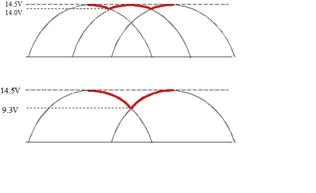
One word commonly used to describe this type of pulsation is "hunting". The voltage regulator sees system voltage going too high. It responds by reducing alternator output, but there's a built-in delay. By the time it lowers output, that output voltage has already been rising for too long. By the time it cuts back, the drop in output overshoots and drops too far before the regulator sees it and catches up. This wasn't a problem in the 1970s when the biggest standard alternators were only good for 55 amps. At most you might see a small dimming of the lights when the AC compressor kicked on, but that was easy to overlook. Today with a computer hung onto every conceivable part of the car, various loads are being switched on and off all the time. The regulator circuit has to be able to respond almost instantly to maintain steady system voltage.
The next thing to look at is the fat, bolted-on output wire from the alternator to the battery's positive post. There will be some type of fuse device in that circuit. It used to be a fuse link wire spliced into that cable, usually very near the battery. Later model vehicles use a regular fuse bolted into the under-hood fuse box. Those bolts can work loose and are a good place to find arced terminals that need to be shined up. Like you did with the ground circuit, measure between the battery's positive post and the stud on the back of the alternator. These tests must be done with the engine running. If you find a significant voltage drop, or if the voltage is pulsing, we have to break the circuit down into a number of smaller sections, and check each one to find the excessive resistance. Expect this voltage to be in the order of possibly as much as 0.2 volts, and it will increase as more high loads, such as heater fans, head lights, and rear window defoggers, are turned on. The maximum allowable is generally 0.4 volts, but I don't like to see that much.
I want to add a comment here for the benefit of others researching this topic. It has to do with digital instrument clusters like most cars have today, and GM vehicles in particular. GM "AC generators" have their voltage regulator built in. They have a whole pile of design problems already, but system voltage sensing becomes an issue with digital dashes. Their voltage regulators monitor output voltage inside the generator, regardless of what's happening in the rest of the vehicle. The sensing wire in the four-pin plug on the side / back is empty. When the vehicle has a digital dash, that sensing wire IS in that plug, and system voltage is monitored remotely right at the instrument cluster. That ensures the dash is fed a stable supply voltage, with whatever happens on the rest of the car less important.
On Chrysler vehicles, there's no need for remote voltage sensing. It's part of the software in the Engine Computer. They call your instrument cluster the MIC", (mechanical instrument cluster). It is immune to voltage fluctuations, except, of course, for the light bulbs in it.
If nothing reduces the pulsing up to now, a possible solution might be to add a large capacitor to the two smaller terminals on the back of the alternator. I'll address that in a minute, but first let me explain how to diagnose this system. I mentioned all the places the ASD relay sends 12 volts to once the engine is running. One of those places is the alternator's field circuit. To generate a voltage and a current mechanically, you need three things; a magnet, a wire, and most importantly, movement between them. We use a coil of wire as it's more efficient. The rotor is an electromagnetic coil, and the movement is we spin that coil with a belt and pulley. There's a number of ways to adjust output, but only one is practical. We can't raise and lower engine speed as the electrical demand changes, but it's easy to adjust the strength of the electromagnetic field coil. At its highest possible output, that field current is only roughly three amps. (That's the three amps that also flows through the regulator's metal case, to ground). Under most typical driving conditions, that field current is only around one to one and a half amps, so it's not real significant. It IS enough, though, to cause a voltage drop across that spinning field coil. To begin testing this system, simply measure the two voltages on the two smaller terminals on the back of the alternator. Of course this has to be done with the engine running. During normal, or proper operation, battery voltage must be between 13.75 and 14.75 volts. I'll use 14 volts for my story. When you measure these two voltages, one of them will be 14 volts. If you find less than battery voltage, there's extremely little to check, basically a few inches of wire, because most of what could cause that would cause the engine to not run. You'd be diagnosing a failure to run, not a charging problem.
Assuming you do find 14 volts, the voltage on the second terminal must be less, but not 0.00 volts. If you find 0.00 volts on that second terminal, the brushes inside the alternator are worn. Those can be replaced, often without even removing the alternator from the engine. Cost of parts is around $12.00. Instead, most people just replace the entire alternator.
If you do find less than 14 volts on the second terminal, the input side of the charging system, including the voltage regulator circuitry, is working. My next story will cover the output side of the charging system, when necessary, but that involves little else besides the alternator itself. Typically, you'll find that second voltage to be between 4 - 11 volts. The lower that voltage is, the greater is the difference between them, meaning the stronger magnetic field is being produced. That means more output current is being developed.
If your regulator circuit in the computer is open, meaning a break in the circuit, you will find exactly the same voltage on both smaller terminals. There's no current flow through the field,coil, so no magnetic field is being developed, and with no current flow, no voltage is dropped across it, so you end up on the second terminal the same as you started with on the first one. This is the condition you're trying to solve.
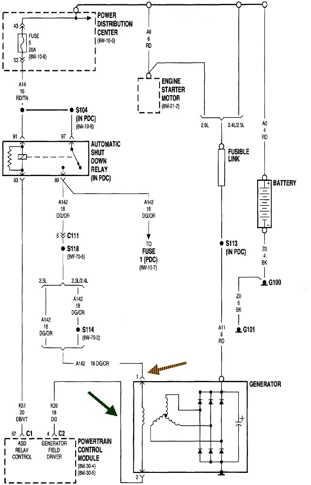
In this diagram, you'll see the feed wire to the field coil is dark green / orange. The "control" wire is dark green. In this story, we've determined the field circuit is open, and it appears you correctly found the defect is inside the Engine Computer. Before going through the work of the modification, (or spending our customer's money), we had better verify the alternator itself is okay and doesn't have an additional problem. A real fast way to do that is with a "full-field" test. All that involves is grounding the dark green wire while the engine is running. Be aware this is definitely no time to raise engine speed. Doing so has the ability to send system voltage well over 30 volts, enough to destroy multiple computers and burn out any bulbs that are turned on. Alternators and generators are very inefficient at low speeds, but if working properly, they will develop plenty of increased voltage to be seen. Monitor battery voltage, or watch the brightness of the head lights when you ground that wire. If voltage goes up, the alternator can be said to have "not failed". It still may not be working to full capacity, but that's a story for another day.
Next, I get to discuss some problems with this dark green wire. This same circuit was used on Dodge Shadows. We had three of them, donated by Chrysler, to my community college, that I used for training. On those models, there was an inline connector halfway between the computer and the alternator. I never did, and never allowed anyone to pierce wire insulation to take measurements. Instead, those connectors made dandy test points. That is a perfect place to touch a jumper wire, and to ground, to full-field the system. If you don't have an inline connector, or know where to find it, you're presented with a new problem. You can do this test right at the back of the alternator, however, both wires go through a black plastic block and emerge as two thin tabs bolted to the two small terminal bolts. When the system is working properly, it's easy to tell which tab goes with which wire by the voltages. It's when you have your problem of an open circuit, both voltages will be exactly the same. Which tab do you ground to perform the full-field test? If you try the correct one first, charging voltage will go up. If you grab the wrong one first, you'll blow the fuse feeding the ASD circuit. No harm done, but it is embarrassing. I do have a relatively simple trick to figure out which is the correct terminal to ground, but I can't give out all me secrets at once.
Okay, as promised, back to my thoughts on adding a capacitor. We're looking for the cause of alternator output going up and down. That is a result of unwanted current flow changes between the two smaller field terminals, and that is caused by unwanted voltage fluctuations between them. A capacitor, for anyone not familiar with them, can be thought of as nothing more than a very small battery. The large ones basically want to oppose a change in voltage across them. Their use in this type of circuit is to absorb the voltage increases, and provide a little current when the voltage drops. It smooths out the voltage. This is not a part I would buy just to experiment. As a former tv / vcr repairman who has scrapped out hundreds of units, I have boxes full of these "prizes". Find any friend who is into electronics, or visit any tv repair shop, if you can still find one, and they will have all you want, probably for free. They're rated in voltage and "microfarads", which is their electrical storage capacity. I'd look for something in the area of 100 to 1000 mfd. The voltage just has to be higher than what it will "see" in the car. Common voltages are 50 and 100 volts. It refers to the voltage it can withstand without arcing and shorting internally. These larger capacitors are referred to as "electrolytics", and as such, they do have a polarity. Get that polarity wrong with so a low voltage, and it's extremely likely nothing exciting will happen. For testing, it will work fine. If possible to figure out, the positive terminal should go to the 14-volt feed terminal, and the negative to the dark green wire / terminal.
If the fluctuations stop with the capacitor installed, that may not necessarily be the solution, but it would be a clue.
There's one more rather important problem with doing this modification. That is the Check Engine light is going to be on all the time. The fault code will be "Field circuit not switching properly". Along with all the things the internal regulator knows by being inside the computer, it's circuitry is also monitored for proper operation. The dark green control wire was disconnected to run to the new regulator. No current will flow through the computer's regulator circuit and that will be detected. There are roughly 2,000 different diagnostic fault codes that can be set. Roughly half of them refer to things that could adversely affect emissions. Those are the codes that turn on the Check Engine light. With unknown or questionable charging system operation, low voltage to the ignition coils and injectors can result in poor engine performance and increased emissions. That's why this code turns the Check Engine light on. A lot of people drive every day with that light on. The problem is to set any fault code, there is always a long list of conditions that must be met. One of those conditions is always that certain other codes can't already be set. A number of the self-tests the computer constantly runs will be temporarily suspended, so a new problem can develop that you have no way of knowing about. Many of those problems can be very minor, but turn expensive if ignored. Mostly that involves overheated catalytic converters. Also, when the original problem is finally repaired properly, all those suspended tests will resume, and that's when the Check Engine light turns right back on and we have to start the diagnosis all over. That makes for frustrated car owners, and frustrated mechanics who had no way of knowing there were other, new problems.
Now that I've shared all this, it occurs to me you weren't looking for a no-charge condition. You found charging voltage to be a fuzz too high. Was there some other symptom you were chasing? 16 volts is a little high, but if the regulator circuitry was shorted, the system voltage would be considerably higher and the battery would be spitting acid and its sides would likely be bulging.
There's two more things to consider. The first is when you added the external regulator, the one to the computer has to be disconnected. The one with the lower "target" voltage will overpower the other one, then the two will fight each other. The most likely symptom of that would be those pulsing lights. A second issue, somewhat hard to explain, is controlling the charging system is not actually done by holding field coil voltage constant. Instead, it is switched from full-on, (maximum output), to fully-off, (no output), about 400 times per second. The percentage of "on-time" to "off-time" is adjusted to change the average output voltage. The resulting pulsing is smoothed out by the battery. (That's another sore point with GM charging systems and repeat generator failures). The external regular switches the same way, called "pulse-width modulation", or "pulse-width dimming", and is why such a tiny, lightweight transistor can control such a high current. Switching current flow off through a coil of wire sets up a huge reverse voltage spike. That's highly desirable in ignition coils, but aged batteries in GM vehicles can't dampen and absorb those spikes. Those spikes are what destroys a lot of their generators and causes elusive engine running problems. On your car, if the original regulator is still in the system, one regulator might be switching on while the other one is switching off. With two different target voltages, the alternator is responding to two different commands. Just like when you would hear a whistle when tuning a really old AM radio, if one regulator is switching at 400 cycles per second, and the other is switching at 399 cycles per second, they'll go in and out of sync and you'd see that as a pulsation of the difference, or one cycle per second.
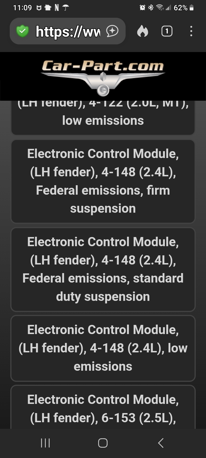
That's getting way more technical than necessary to solve this. First, be sure the internal regulator is not connected at the same time. If you aren't sure, just unplug one of the wires on the external regulator. If the charging system keeps working, there may not actually be anything wrong with the computer. For my better comment of value, given the age of the car, I would seriously consider finding a used Engine Computer from a salvage yard. There will be plenty in the pick-your-own-parts yards. Do a search for "Pull-A-Part" to see if there's one in your area. I've been to 16 of them. All are very clean and well-organized. The last computer I bought for one of my vehicles cost $25.00.
Let me know if that helps or if you have more questions.
Dec 24, 2025 at 6:20 PM