Thank you for the reply and as suspected, darn U codes. Those are a lot of codes. I believe we need to focus on U0001 Can C Bus. Diagnosis shows if every test is good then the front control module will need to be replaced. But since it looks like you had body work you may need an engine harness. Here is what needs to be checked..
Collision
48
2006 Dodge Charger
V8-5.7L VIN H
Body Control System
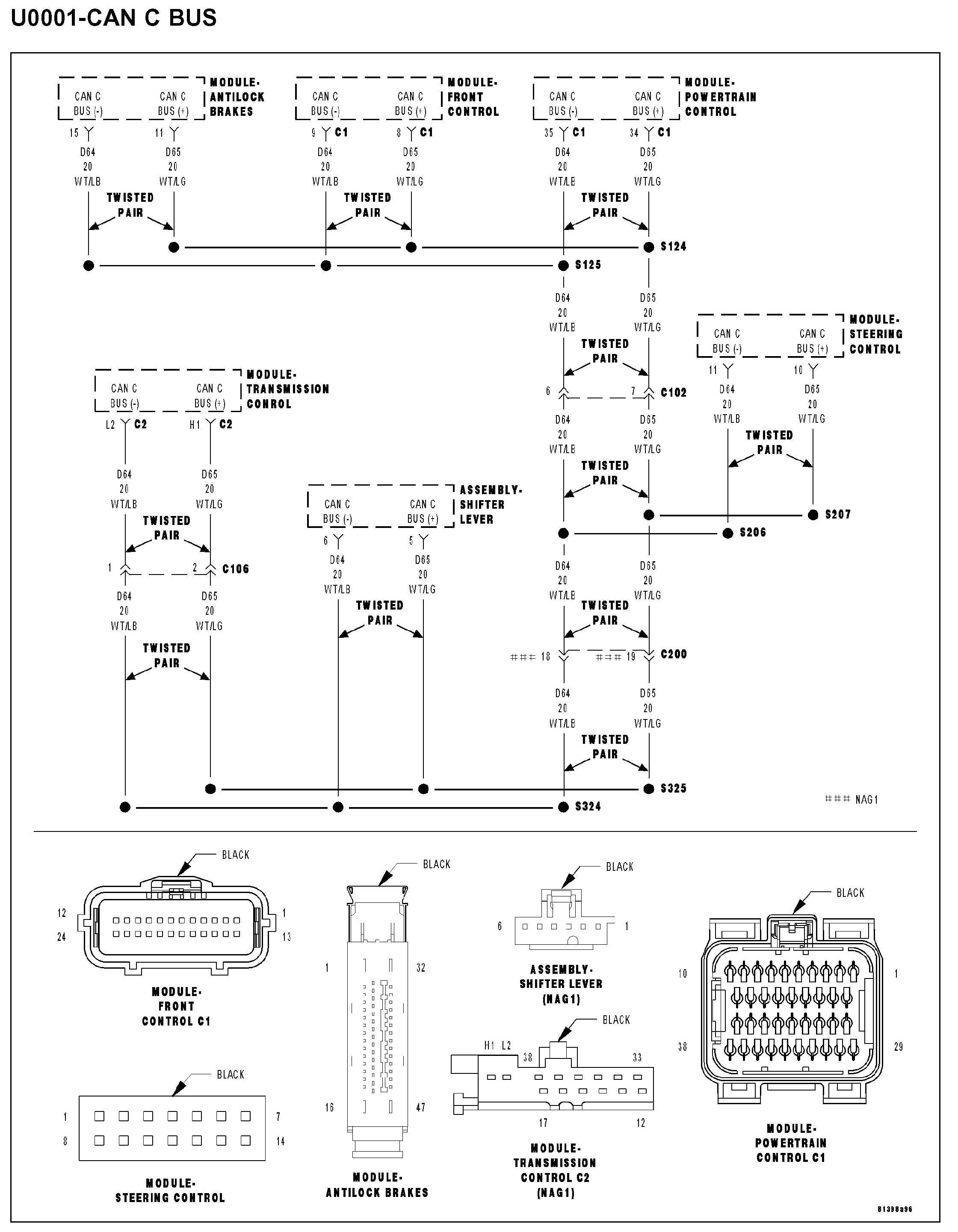
Vehicle ALL Diagnostic Trouble Codes ( DTC ) Testing and Inspection U Code Charts U0001 Body Control System
BODY CONTROL SYSTEM
U0001-CAN C BUS
U0001 - Can C Bus
Open In New TabZoom/Print
WHEN MONITORED
With the ignition on.
SET CONDITION
The FCM detects a short in either CAN C Bus circuit.
POSSIBLE CAUSES
- (D65) CAN C BUS (+) circuit shorted to ground
- (D64) CAN C BUS (-) circuit shorted to ground
- (D65) CAN C BUS (+) circuit shorted to voltage
- (D64) CAN C BUS (-) circuit shorted to voltage
- (D65) CAN C BUS (+) circuit shorted to (D64) CAN C BUS (-) circuit
- Antilock brake module
- Powertrain control module
- Shifter lever assembly (NAG1 only)
- Transmission control module (NAG1 only)
- Steering control module
- Front control module
DIAGNOSTIC TEST
1. TEST FOR INTERMITTENT CONDITION
Turn the ignition on.
With the scan tool, record and erase FCM DTC's.
Cycle the ignition from on to off 3 times.
Turn the ignition on.
With the scan tool, read active FCM DTC's.
Q: Does the scan tool display U0001-CAN C BUS as active?
YES: Go To 2
NO: The conditions that caused this code to set are not present at this time. Using the wiring diagram/schematic as a guide, inspect the wiring and connectors.
2. ANTILOCK BRAKE MODULE - INTERNAL SHORT
Turn the ignition off.
Disconnect the Antilock Brake Module harness connector.
Turn the ignition on.
With the scan tool, record and erase FCM DTC's.
Cycle the ignition from on to off 3 times.
Turn the ignition on.
With the scan tool, read active FCM DTC's.
Q: Does the scan tool display U0001-CAN C BUS as active?
YES: Go To 3
NO: Inspect the wiring and connectors for damage or shorted circuits. If ok, replace the Antilock Brake Module.
Perform ABS VERIFICATION TEST - VER 1. See: A L L Diagnostic Trouble Codes ( DTC ) > Verification Tests > ABS Verification Test
3. POWERTRAIN CONTROL MODULE - INTERNAL SHORT
Turn the ignition off.
Disconnect the Powertrain Control Module C1 harness connector.
Turn the ignition on.
With the scan tool, record and erase FCM DTC's.
Cycle the ignition from on to off 3 times.
Turn the ignition on.
With the scan tool, read active FCM DTC's.
Q: Does the scan tool display U0001-CAN C BUS as active?
YES: Go To 4
NO: Inspect the wiring and connectors for damage or shorted circuits. If ok, replace and program the Powertrain Control Module.
Perform (NGC) POWERTRAIN VERIFICATION TEST VER - 5. See: A L L Diagnostic Trouble Codes ( DTC ) > Verification Tests > Powertrain Verification Test - Ver 5
4. SHIFTER LEVER ASSEMBLY (NAG1 ONLY) - INTERNAL SHORT
Turn the ignition off.
NOTE: If the vehicle is not equipped with a NAG1 controller then skip this step.
Disconnect the Shifter Lever Assembly harness connector.
Turn the ignition on.
With the scan tool, record and erase FCM DTC's.
Cycle the ignition from on to off 3 times.
Turn the ignition on.
With the scan tool, read active FCM DTC's.
Q: Does the scan tool display U0001-CAN C BUS as active?
YES: Go To 5
NO: Inspect the wiring and connectors for damage or shorted circuits. If ok, replace and program the Shifter Lever Assembly.
Perform NAG1 TRANSMISSION VERIFICATION TEST - VER 1. See: A L L Diagnostic Trouble Codes ( DTC ) > Verification Tests > NAG1 Transmission Verification Test
5. TRANSMISSION CONTROL MODULE (NAG1 ONLY) - INTERNAL SHORT
Turn the ignition off.
NOTE: If the vehicle is not equipped with a NAG1 controller then skip this step.
Disconnect the Transmission Control Module C2 harness connector.
Turn the ignition on.
With the scan tool, record and erase FCM DTC's.
Cycle the ignition from on to off 3 times.
Turn the ignition on.
With the scan tool, read active FCM DTC's.
Q: Does the scan tool display U0001-CAN C BUS as active?
YES: Go To 6
NO: Inspect the wiring and connectors for damage or shorted circuits. If ok, replace and program the Transmission Control Module.
Perform NAG1 TRANSMISSION VERIFICATION TEST - VER 1. See: A L L Diagnostic Trouble Codes ( DTC ) > Verification Tests > NAG1 Transmission Verification Test
6. STEERING CONTROL MODULE - INTERNAL SHORT
Turn the ignition off.
Disconnect/remove the Steering Control Module harness connector.
Turn the ignition on.
With the scan tool, record and erase FCM DTC's.
Cycle the ignition from on to off 3 times.
Turn the ignition on.
With the scan tool, read active FCM DTC's.
Q: Does the scan tool display U0001-CAN C BUS as active?
YES: Go To 7
NO: Inspect the wiring and connectors for damage or shorted circuits. If ok, replace and program the Steering Control Module.
Perform BODY VERIFICATION TEST - VER 1. See: A L L Diagnostic Trouble Codes ( DTC ) > Verification Tests > Body Verification Test
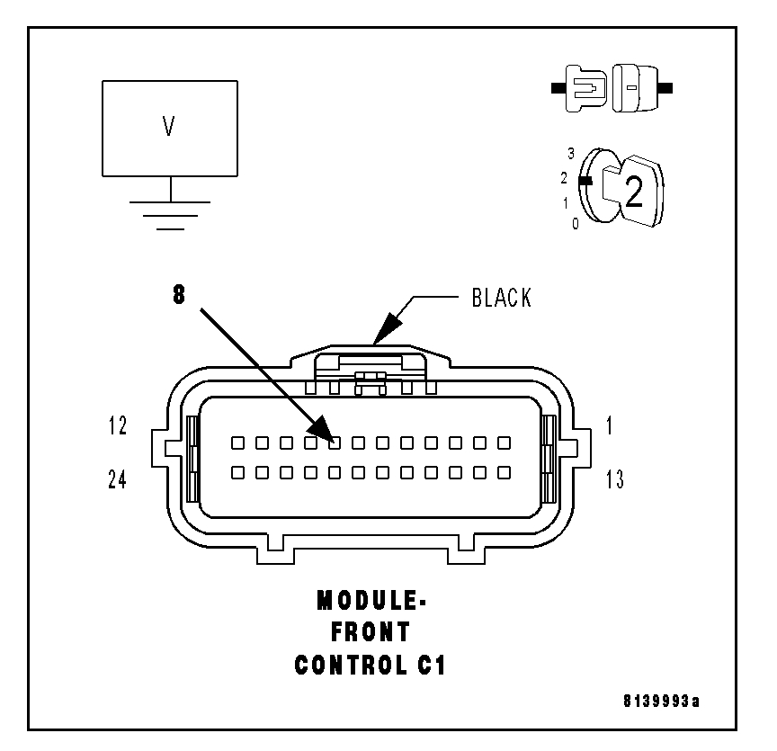
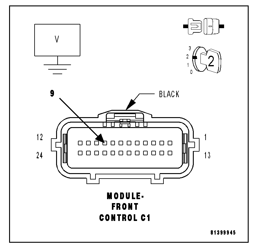
7. (D65) CAN C BUS (+) CIRCUIT SHORTED TO VOLTAGE
Open In New TabZoom/Print
Turn the ignition off.
Disconnect the Front Control Module C1 harness connector.
Turn the ignition on.
Measure the voltage between the (D65) CAN C Bus (+) circuit and ground.
Q: Is there any voltage present?
YES: Repair the (D65) CAN C Bus (+) circuit for a short to voltage.
Perform BODY VERIFICATION TEST - VER 1. See: A L L Diagnostic Trouble Codes ( DTC ) > Verification Tests > Body Verification Test
NO: Go To 8
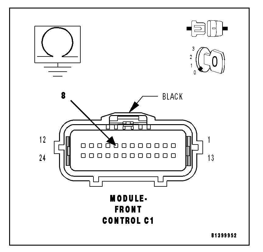
8. (D64) CAN C BUS (-) CIRCUIT SHORTED TO VOLTAGE
Open In New TabZoom/Print
Measure the voltage between the (D64) CAN C Bus (-) circuit and ground.
Q: Is there any voltage present?
YES: Repair the (D64) CAN C Bus (-) circuit for a short to voltage.
Perform BODY VERIFICATION TEST - VER 1. See: A L L Diagnostic Trouble Codes ( DTC ) > Verification Tests > Body Verification Test
NO: Go To 9
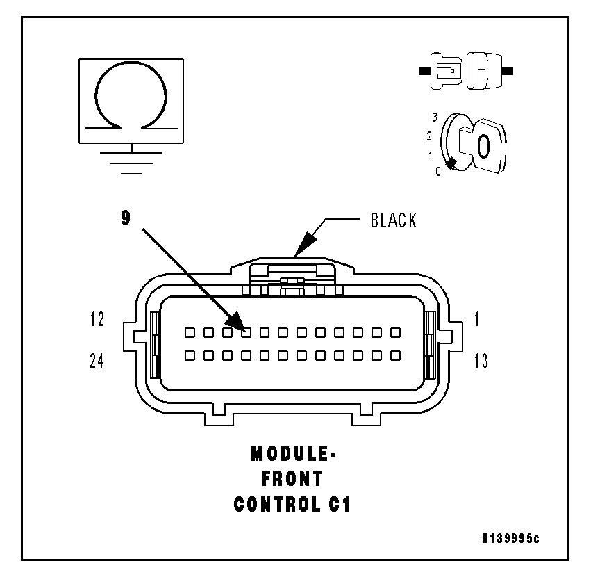
9. (D65) CAN C BUS (+) CIRCUIT SHORTED TO GROUND
Open In New TabZoom/Print
Turn the ignition off.
Measure the resistance between ground and the (D65) CAN C Bus (+) circuit.
Q: Is any resistance present?
YES: Repair the (D65) CAN C Bus (+) circuit for a short to ground.
Perform BODY VERIFICATION TEST - VER 1. See: A L L Diagnostic Trouble Codes ( DTC ) > Verification Tests > Body Verification Test
NO: Go To 10
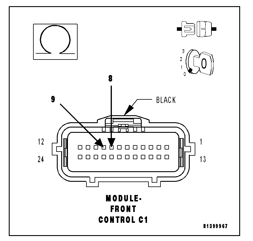
10. (D64) CAN C BUS (-) CIRCUIT SHORTED TO GROUND
Open In New TabZoom/Print
Measure the resistance between ground and the (D64) CAN C Bus (-) circuit.
Q: Is any resistance present?
YES: Repair the (D64) CAN C Bus (-) circuit for a short to ground.
Perform BODY VERIFICATION TEST - VER 1. See: A L L Diagnostic Trouble Codes ( DTC ) > Verification Tests > Body Verification Test
NO: Go To 11
11. (D65) CAN C BUS (+) CIRCUIT SHORTED TO (D64) CAN C BUS (-) CIRCUIT
Open In New TabZoom/Print
Measure the resistance between the (D65) CAN C Bus (+) circuit and the (D64) CAN C Bus (-) circuit.
Q: Is any resistance present?
YES: Repair the (D65) CAN C Bus (+) circuit for a short to the (D64) CAN C Bus (-) circuit.
Perform BODY VERIFICATION TEST - VER 1. See: A L L Diagnostic Trouble Codes ( DTC ) > Verification Tests > Body Verification Test
NO: Inspect the wiring and connectors for damage or shorted circuits. If ok, replace and program the Front Control Module.
Perform BODY VERIFICATION TEST - VER 1. See: A L L Diagnostic Trouble Codes ( DTC ) > Verification Tests > Body Verification Test
Something like this and especially if you may have been in a collision I recommend you go through your insurance since diagnostic like this can be very expensive. I have seen this too many times where a vehicle comes in especially with a salvage title where diagnosing network problems because a body shop solder something wrong painted over a ground point, or wires are damaged that it makes it very difficult to diagnose and very expensive.
If your mechanic is up to the challenge then the info I gave you should give them a starting point. But he may decline because of the work will take way too long without charging hours of diagnosis. I am sorry if this is not the news you wanted to hear but every wire on that procedure, every connector that needs to be disconnected and resetting codes to see what comes back on is very difficult to pinpoint. The C Bus failure pretty much narrows down all the module faults you have posted.
Images (Click to enlarge)
Sep 10, 2019 at 11:48 PM