Is there a suffix code for either of those two? The B0090 could be one of 5 different issues all relating to the left front impact sensor
B0090:11 - Left Frontal Restraints Sensor: Circuit Short to Ground
B0090:4A - Left Frontal Restraints Sensor: Incorrect Component Installed
B0090:81 - Left Frontal Restraints Sensor: Invalid Serial Data Received
B0090:93 - Left Frontal Restraints Sensor: No Operation
B0090:96 - Left Frontal Restraints Sensor: Component Internal Failure
The 4A and 81 codes are common if the replacement part is not the OE specific part for that exact truck, they are seen a lot if a factory part isn't used. These can be verified using an OE level scan tool that can talk to the SRS module and extract that data.
The 11 and 96 sections require a scan tool that can read the data pids to determine what the RCM is seeing for resistance on the circuit. This cannot be tested without that ability.
The Restraints Control Module (RCM) continuously monitors the passenger air bag module stage 2 circuits for the following faults:
Resistance out of range
Unexpected voltage
Short to ground
Faulted passenger air bag module
If a fault is detected, the RCM stores DTC B0011:11, B0011:12, B0011:13 or B0011:1A in memory and sends a message to the Instrument Panel Cluster (IPC) module to illuminate the air bag warning indicator.
The RCM analyzes the deployment loop resistance and uses this measurement in combination with an age correction factor to determine if a fault exists. The value displayed in the PID is the deployment loop resistance as measured by the RCM. If the value displayed is lower or higher than the desired range (refer to diagram below), the RCM can set a DTC. As the deployment loop resistance drifts farther outside the desired range, the chance for a DTC increases. The RCM fault trigger threshold may vary as the vehicle ages. Small variations in resistance can occur due to the effect of road vibrations on terminal fit and/or temperature changes. These variables can result in an intermittent fault. For this reason, the test requires the PID value to be within the desired range before the fault is considered repaired, regardless if the module is reporting an on-demand DTC at the time of diagnosis. Following this direction helps make sure that minor changes in resistance do not create a repeat concern. This test uses process of elimination to diagnose each part of the deployment loop circuit including:
Wiring
Connections
Passenger air bag module
RCM
It monitors for a resistance range of 1.7 to 2.78 ohms, outside of this range a code will set.
B0011:11 � Passenger Frontal Stage 2 Deployment Control: Circuit Short to Ground
A fault is indicated when the RCM senses a short to ground on either passenger air bag stage 2 circuit.
B0011:12 � Passenger Frontal Stage 2 Deployment Control: Circuit Short to Battery
A fault is indicated when the RCM senses a short to voltage on either passenger air bag stage 2 circuit.
B0011:13 � Passenger Frontal Stage 2 Deployment Control: Circuit Open
A fault is indicated when the RCM measures greater than the desired resistance range between passenger air bag stage 2 circuits.
B0011:1A � Passenger Frontal Stage 2 Deployment Control: Circuit Resistance Below Threshold
A fault is indicated when the RCM measures less than the desired resistance range between passenger air bag stage 2 circuits.
This pinpoint test is intended to diagnose the following:
Wiring, terminals or connectors
Passenger air bag module
RCM
PINPOINT TEST E : DTCs B0011:11, B0011:12, B0011:13 AND B0011:1A
WARNING: Do not handle, move or change the original horizontal mounting position of the restraints control module (RCM) while the RCM is connected and the ignition switch is ON. Failure to follow this instruction may result in the accidental deployment of the Safety Canopy and cause serious personal injury or death.
WARNING: Never probe the electrical connectors on airbag, Safety Canopy or side air curtain assemblies. Failure to follow this instruction may result in the accidental deployment of these assemblies, which increases the risk of serious personal injury or death.
NOTICE: Use the correct probe adapter(s) from the Flex Probe Kit when taking measurements. Failure to use the correct probe adapter(s) may damage the connector.
NOTE: Most faults are due to connector and/or wiring concerns. Carry out a thorough inspection and verification before proceeding with the pinpoint test.
NOTE: Only disconnect or reconnect Supplemental Restraint System (SRS) components when instructed to do so within a pinpoint test step. Failure to follow this instruction may result in incorrect diagnosis of the SRS.
NOTE: Always make sure the correct SRS component is being installed. Parts released for other vehicles may not be compatible even if they appear physically similar. Check the part number listed in the parts catalog to make sure the correct component is being installed. If an incorrect SRS component is installed, DTCs may set.
Enter the following diagnostic mode on the scan tool: Self Test � RCM.
Was DTC B0011:11, B0011:12, B0011:13 or B0011:1A retrieved on-demand during self-test?
Yes This fault cannot be cleared until it is corrected and the DTC is no longer retrieved on-demand during self-test.
For DTC B0011:13 or B0011:1A, GO to E2.
For DTC B0011:11, GO to E8.
For DTC B0011:12, GO to E10.
No This is an intermittent fault when present as a Continuous Memory Diagnostic Trouble Code (CMDTC) only.
For DTC B0011:13 or B0011:1A, GO to E13.
For DTC B0011:11, GO to E14.
For DTC B0011:12, GO to E15.
E2 CHECK THE PASSENGER FRONTAL STAGE 2 DEPLOYMENT CONTROL RESISTANCE (DEPLOY_06_R) PID
Enter the following diagnostic mode on the scan tool: DataLogger � RCM.
Monitor and record PID DEPLOY_06_R.
Does the PID value read between 1.7 and 2.78 ohms?
Yes GO to E12.
No GO to E3.
E3 CHECK THE PASSENGER FRONTAL STAGE 2 DEPLOYMENT CONTROL RESISTANCE (DEPLOY_06_R) PID WHILE CARRYING OUT THE HARNESS TEST
While monitoring the DEPLOY_06_R PID, carry out the harness test of the passenger air bag module circuits and accessible connectors (including any in-line connectors), by wiggling connectors and flexing the wire harness frequently.
Does the PID value read between 1.7 and 2.78 ohms while carrying out the harness test?
Yes DEPOWER the SRS and REPAIR the connector, terminals or wire harness as needed.
Refer to Wiring Diagrams Cell 5, Connector Repair Procedures for schematic and connector information.
GO to E17.
No For PID value less than 1.7 ohms, GO to E4.
For PID value greater than 2.78 ohms, GO to E6.
E4 CHECK THE PASSENGER FRONTAL STAGE 2 DEPLOYMENT CONTROL DTC FOR A FAULT STATUS CHANGE (LOW RESISTANCE INDICATED)
NOTE: This pinpoint test step attempts to change the fault reported by the RCM by inducing a different fault condition. If the fault reported changes, this indicates the RCM is functioning correctly and is not the source of the fault.
Ignition OFF.
Depower the SRS. Refer to Supplemental Restraint System (SRS) Depowering and Repowering in this section.
Disconnect: Passenger Air Bag Module C256A and C256B.
Repower the SRS. Do not prove out the SRS at this time. Refer to Supplemental Restraint System (SRS) Depowering and Repowering in this section.
Ignition ON.
Enter the following diagnostic mode on the scan tool: Self Test � RCM.
DIAGNOSTIC TIP: When viewing DTCs with the passenger air bag module disconnected, open circuit faults are normally retrieved on passenger air bag stages 1 and 2.
Did the on-demand DTC change from B0011:1A to B0011:13?
Yes GO to E11.
No GO to E5.
E5 CHECK FOR A SHORT BETWEEN PASSENGER AIR BAG STAGE 2 CIRCUITS
Ignition OFF.
Depower the SRS. Refer to Supplemental Restraint System (SRS) Depowering and Repowering in this section.
Disconnect: RCM C310A and C310B.
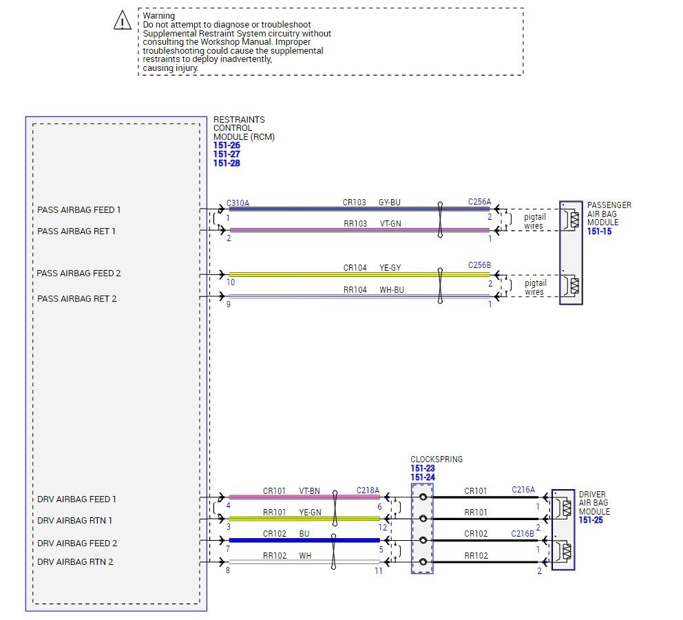
Measure the resistance between C256B-2, circuit CR104 (YE/GY), harness side and C256B-1, circuit RR104 (WH/BU), harness side.
Is the resistance greater than 10,000 ohms?
Yes GO to E12.
No REPAIR circuits CR104 (YE/GY) and RR104 (WH/BU).
Refer to Wiring Diagrams Cell 5 for schematic and connector information.
GO to E17.
E6 CHECK THE PASSENGER AIR BAG STAGE 2 CIRCUITS FOR AN OPEN
Ignition OFF.
Depower the SRS. Refer to Supplemental Restraint System (SRS) Depowering and Repowering in this section.
Disconnect: Passenger Air Bag Module C256A and C256B.
Disconnect: RCM C310A and C310B.
Measure the resistance between RCM C310A, harness side and passenger air bag module C256B, harness side using the following chart.
RCM Circuit Passenger Air Bag Module Stage 2 Electrical Connector
C310A-10 CR104 (YE/GY) C256B-2
C310A-9 RR104 (WH/BU) C256B-1
imageOpen In New TabZoom/Print
Are the resistances less than 0.5 ohm?
Yes GO to E7.
No REPAIR circuit CR104 (YE/GY) or RR104 (WH/BU).
Refer to Wiring Diagrams Cell 5 for schematic and connector information.
GO to E17.
E7 CHECK THE PASSENGER FRONTAL STAGE 2 DEPLOYMENT CONTROL DTC FOR A FAULT STATUS CHANGE (OPEN INDICATED)
NOTE: This pinpoint test step attempts to change the fault reported by the RCM by inducing a different fault condition. If the fault reported changes, this indicates the RCM is functioning correctly and is not the source of the fault.
Connect: RCM C310A and C310B.
Connect a fused jumper wire between passenger air bag module stage 2 C218A-2, circuit CR104 (YE/GY), harness side, and C218A-1, circuit RR104 (WH/BU), harness side.
ImageOpen In New TabZoom/Print
Repower the SRS. Do not prove out the SRS at this time. Refer to Supplemental Restraint System (SRS) Depowering and Repowering in this section.
Ignition ON.
Enter the following diagnostic mode on the scan tool: Self Test � RCM.
DIAGNOSTIC TIP: When viewing DTCs with the passenger air bag module stage 2 circuits shorted together, a low resistance fault is normally retrieved on stage 2. Stage 1 shows an open circuit fault due to the passenger air bag module being disconnected.
Did the on-demand DTC change from B0011:13 to B0011:1A?
Yes REMOVE the fused jumper wire and GO to E11.
No REMOVE the fused jumper wire and GO to E12.
E8 CHECK THE PASSENGER FRONTAL STAGE 2 DEPLOYMENT CONTROL DTC FOR A FAULT STATUS CHANGE (SHORT TO GROUND INDICATED)
NOTE: This pinpoint test step attempts to change the fault reported by the RCM by inducing a different fault condition. If the fault reported changes, this indicates the RCM is functioning correctly and is not the source of the fault.
Ignition OFF.
Depower the SRS. Refer to Supplemental Restraint System (SRS) Depowering and Repowering in this section.
Disconnect: Passenger Air Bag Module C256A and C256B.
Repower the SRS. Do not prove out the SRS at this time. Refer to Supplemental Restraint System (SRS) Depowering and Repowering in this section.
Ignition ON.
Enter the following diagnostic mode on the scan tool: Self Test � RCM.
DIAGNOSTIC TIP: When viewing DTCs with the passenger air bag module disconnected, open circuit faults are normally retrieved on stages 1 and 2.
Did the on-demand DTC change from B0011:11 to B0011:13?
Yes GO to E11.
No GO to E9.
E9 CHECK THE PASSENGER AIR BAG STAGE 2 CIRCUITS FOR A SHORT TO GROUND
Ignition OFF.
Depower the SRS. Refer to Supplemental Restraint System (SRS) Depowering and Repowering in this section.
Disconnect: RCM C310A and C310B.
Measure the resistance between passenger air bag module:
C256B-2, circuit CR104 (YE/GY), harness side and ground.
C256B-1, circuit RR104 (WH/BU), harness side and ground.
ImageOpen In New TabZoom/Print
Are the resistances greater than 10,000 ohms?
Yes GO to E12.
No REPAIR circuit CR104 (YE/GY) or RR104 (WH/BU).
Refer to Wiring Diagrams Cell 5 for schematic and connector information.
GO to E17.
E10 CHECK THE PASSENGER AIR BAG STAGE 2 CIRCUITS FOR A SHORT TO VOLTAGE
Ignition OFF.
Depower the SRS. Refer to Supplemental Restraint System (SRS) Depowering and Repowering in this section.
Disconnect: Passenger Air Bag Module C256A and C256B.
Disconnect: RCM C310A and C310B.
Repower the SRS. Do not prove out the SRS at this time. Refer to Supplemental Restraint System (SRS) Depowering and Repowering in this section.
Ignition ON.
Measure the voltage between passenger air bag module:
C256B-2, circuit CR104 (YE/GY), harness side and ground.
C256B-1, circuit RR104 (WH/BU), harness side and ground.
ImageOpen In New TabZoom/Print
Is voltage present on either circuit?
Yes REPAIR circuit CR104 (YE/GY) or RR104 (WH/BU).
Refer to Wiring Diagrams Cell 5 for schematic and connector information.
GO to E17.
No GO to E12.
E11 CONFIRM THE PASSENGER AIR BAG MODULE FAULT
NOTE: Make sure all restraint system components and the RCM electrical connectors are connected before carrying out the self-test. If not, DTCs will be recorded.
Ignition OFF.
Depower the SRS. Refer to Supplemental Restraint System (SRS) Depowering and Repowering in this section.
Connect: Passenger Air Bag Module C256A and C256B (if previously disconnected).
Repower the SRS. Do not prove out the SRS at this time. Refer to Supplemental Restraint System (SRS) Depowering and Repowering in this section.
Ignition ON.
Enter the following diagnostic mode on the scan tool: Self Test � RCM.
Was the original DTC retrieved on-demand during self-test?
Yes INSTALL a new passenger air bag module. REFER to Passenger Airbag in this section. GO to E17.
No In the process of diagnosing the fault, the fault condition has become intermittent. Do not install any new SRS components at this time. Install SRS components only when directed to do so in the pinpoint test.
For DTC B0011:13 or B0011:1A, GO to E13.
For DTC B0011:11, GO to E14.
For DTC B0011:12, GO to E15.
E12 CONFIRM THE RCM FAULT
NOTE: Make sure all restraint system components and the RCM electrical connectors are connected before carrying out the self-test. If not, DTCs will be recorded.
Ignition OFF.
Depower the SRS. Refer to Supplemental Restraint System (SRS) Depowering and Repowering in this section.
Prior to reconnecting any previously disconnected SRS component:
inspect connector(s) (including any in-line connectors) for pushed-out, loose or spread terminals and loose or frayed wire connections at terminals.
Inspect wire harness for any damage, pinched, cut or pierced wires.
Inspect RCM C310A and C310B Connector Position Assurance (CPA) lever/lock for correct operation. Refer to Restraints Control Module (RCM) in this section.
Repair any concerns found.
Refer to Wiring Diagrams Cell 5, Connector Repair Procedures for schematic and connector information.
Connect: Passenger Air Bag Module C256A and C256B (if previously disconnected).
Connect: RCM C310A and C310B.
Repower the SRS. Do not prove out the SRS at this time. Refer to Supplemental Restraint System (SRS) Depowering and Repowering in this section.
Ignition ON.
Enter the following diagnostic mode on the scan tool: Self Test � RCM.
Was the original DTC retrieved on-demand during self-test?
Yes INSTALL a new RCM. REFER to Restraints Control Module (RCM) in this section. GO to E17.
No In the process of diagnosing the fault, the fault condition has become intermittent. Do not install any new SRS components at this time. Install SRS components only when directed to do so in the pinpoint test.
For DTC B0011:13 or B0011:1A, GO to E13.
For DTC B0011:11, GO to E14.
For DTC B0011:12, GO to E15.
E13 CHECK THE PASSENGER FRONTAL STAGE 2 DEPLOYMENT CONTROL RESISTANCE (DEPLOY_06_R) PID FOR AN INTERMITTENT LOW RESISTANCE OR OPEN CIRCUIT FAULT
Enter the following diagnostic mode on the scan tool: DataLogger � RCM.
Monitor and record PID DEPLOY_06_R.
Attempt to recreate the fault by wiggling connectors (including any in-line connectors) and flexing the wire harness frequently.
Does the PID value read between 1.7 and 2.78 ohms?
Yes The fault is not present and cannot be recreated at this time. Do not install any new SRS components at this time. Install SRS components only when directed to do so in the pinpoint test. GO to E16.
No DEPOWER the SRS and REPAIR as necessary.
Refer to Wiring Diagrams Cell 5, Connector Repair Procedures for schematic and connector information.
GO to E17.
E14 CHECK THE PASSENGER FRONTAL STAGE 2 DEPLOYMENT CONTROL FOR AN INTERMITTENT SHORT TO GROUND FAULT
Attempt to recreate the fault by wiggling connectors (including any in-line connectors) and flexing the wire harness frequently.
Enter the following diagnostic mode on the scan tool: Self Test � RCM.
Was DTC B0011:11 retrieved on-demand during self-test?
Yes DEPOWER the SRS and REPAIR as necessary.
Refer to Wiring Diagrams Cell 5, Connector Repair Procedures for schematic and connector information.
GO to E17.
No The fault is not present and cannot be recreated at this time. Do not install any new SRS components at this time. Install SRS components only when directed to do so in the pinpoint test. GO to E16.
E15 CHECK THE PASSENGER FRONTAL STAGE 2 DEPLOYMENT CONTROL FOR AN INTERMITTENT SHORT TO BATTERY FAULT
Ignition OFF.
Depower the SRS. Refer to Supplemental Restraint System (SRS) Depowering and Repowering in this section.
Disconnect: Passenger Air Bag Module C256A and C256B.
Repower the SRS. Do not prove out the SRS at this time. Refer to Supplemental Restraint System (SRS) Depowering and Repowering in this section.
Ignition ON.
Attempt to recreate the fault by wiggling connectors (including any in-line connectors) and flexing the wire harness frequently.
Enter the following diagnostic mode on the scan tool: Self Test � RCM.
Was DTC B0011:12 retrieved on-demand during self-test?
Yes DEPOWER the SRS and REPAIR as necessary.
Refer to Wiring Diagrams Cell 5, Connector Repair Procedures for schematic and connector information.
GO to E17.
No The fault is not present and cannot be recreated at this time. Do not install any new SRS components at this time. Install SRS components only when directed to do so in the pinpoint test. GO to E16.
E16 CHECK THE HARNESS AND CONNECTORS
Ignition OFF.
Depower the SRS. Refer to Supplemental Restraint System (SRS) Depowering and Repowering in this section.
Disconnect: Passenger Air Bag Module C256A (if not previously disconnected).
Disconnect: Passenger Air Bag Module C256B (if not previously disconnected).
Inspect connector(s) (including any in-line connectors) for corrosion, loose or spread terminals and loose or frayed wire connections at terminals.
Inspect wire harness for any damage, pinched, cut or pierced wires.
Inspect RCM C310A and C310B CPA lever/lock for correct operation. Refer to Restraints Control Module (RCM) in this section.
Were any concerns found?
Yes REPAIR as necessary.
Refer to Wiring Diagrams Cell 5, Connector Repair Procedures for schematic and connector information.
GO to E17.
No The fault is not present and cannot be recreated at this time. Do not install any new SRS components at this time. Install SRS components only when directed to do so in the pinpoint test. GO to E17.
E17 CHECK FOR ADDITIONAL SRS DTCs
Ignition OFF. Image WARNING: Turn the ignition OFF and wait one minute to deplete the backup power supply. Failure to follow this instruction may result in serious personal injury or death in the event of an accidental deployment.
Reconnect all SRS components (if previously disconnected).
If previously directed to depower the SRS, repower the SRS. Do not prove out the SRS at this time. Refer to Supplemental Restraint System (SRS) Depowering and Repowering in this section.
Ignition ON.
Enter the following diagnostic mode on the scan tool: Self Test � Restraints. NOTE: When selecting Restraints from the Self Test menu, DTCs are retrieved from the RCM and OCSM.
Are any RCM and/or OCSM DTCs retrieved on-demand during self-test?
Yes Do not clear any DTCs until all DTCs have been resolved. GO to the DTC Charts in this section for pinpoint test direction.
No CLEAR all RCM and OCSM CMDTCs.
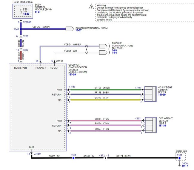
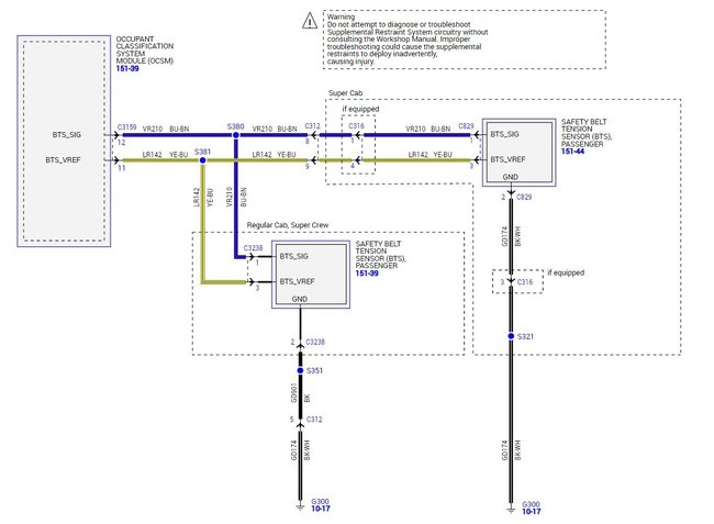
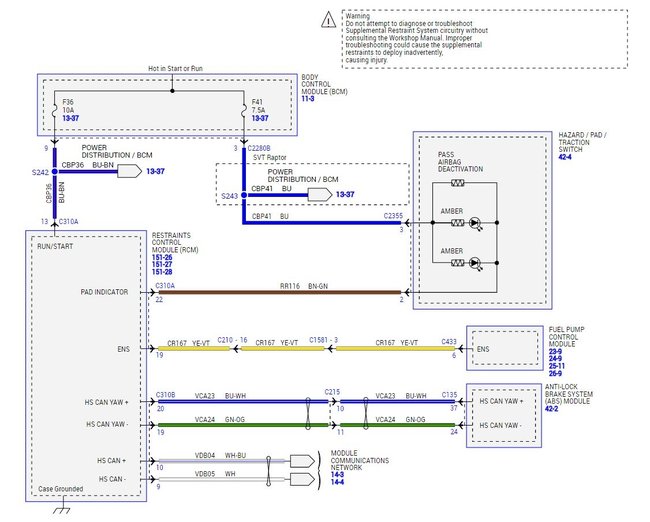
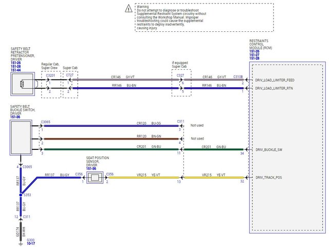
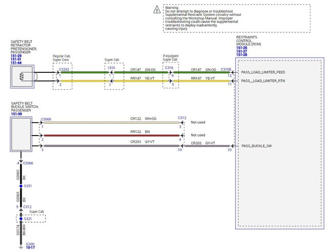
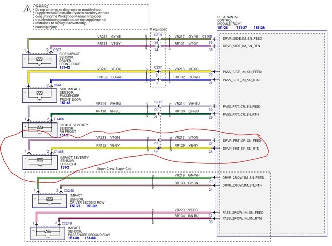
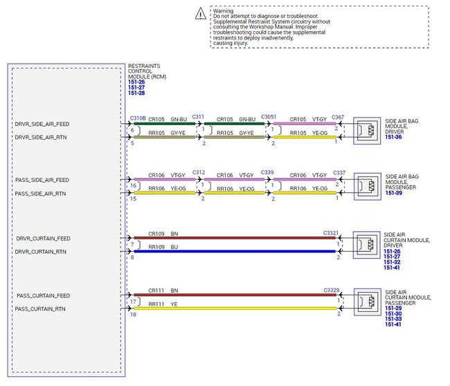
Attached are the wiring diagrams for the testing, depending on which section of the E tests you need to do. The testing in most cases uses a scan tool and a multimeter to measure the voltages at the various connections as the scan tool cycles the tests or reads the results through the RCM.
You mentioned changing one of the sensors, was it the left (drivers side) or right one that you changed?
P1703 can be one of two different issues,
P1703 - Brake Switch Out of Self Test Range
P1703 - Powertrain Control/Emissions Diagnosis (PC/ED)
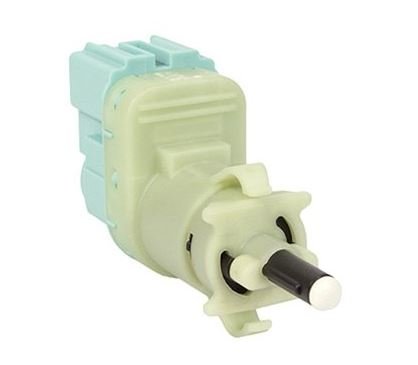
The P1703 code however is most likely a brake pedal position sensor issue.
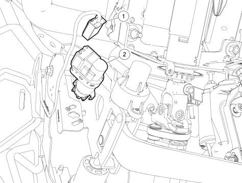
There was a recall done on these trucks for it and it involved replacing the switch to repair the problem. The switch is very easy to replace. If you look under the dash at the hanger assembly for the brake pedal you will see the switch. To replace it you disconnect the wire connection, the turn the switch body about 1/8 of a turn counterclockwise to release it, then just pull it out. Reverse the process to install the new one.
Images (Click to make bigger)
Wednesday, February 24th, 2021 AT 2:05 PM

