A/C compressor clutch not getting signal to turn on?

Tiny
RJESTEADT
  • MEMBER
  • 2005 NISSAN ARMADA
  • 260,000 MILES
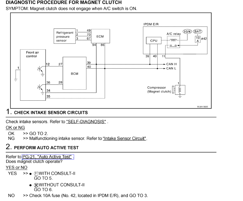
The Nissan self-test IPDM test. Shows that the A/C clutch does work. When you do the test, the clutch does activate. There is refrigerant in the system with proper pressures.

High pressure condenser switch has been replaced. The TCA thermal control amp is also called Sun loan sensor. The one that has that sits in the evaporator box that has been checked and tested with an accurate oh meter of 19,000 homes at 90°F so I think I’ve ruled that out.

The A/C does work and blows cold air. If I run a jumper wire to the A/C clutch without the jumper wire, the A/C clutch will not engage. It’s not getting signal even though the IP DM test shows that it works.

I would think the IP DM test checks, all relays, fuses and sensors, but I don’t know I have checked manually relays and fuses that I am aware of by following the schematic on the fuse box cover.
Saturday, February 22nd, 2025 AT 8:34 AM

7 Replies

Tiny
CANNON1349
  • MECHANIC
  • 783 POSTS
Hello, if the self-test can engage the clutch, then the relay is good. The relay is an internal component of the IPDM. This also means the fuses are good. This pretty much leaves climate control unit not sending the proper request to the body control module. I will attach the instructions for removal of the module below, the procedure is the same for both Automatic and Manual HVAC systems.

Automatic and Manual HVAC
Removal
1. Remove the five control knobs from the front air control unit.
2. Remove the cluster lid C. Refer to "CLUSTER LID C".

(See image 1)

3. Remove the four screws securing the front air control unit to cluster lid C.
4. Remove the front air control unit.

Please let us know how it turns out!
William
Was this
answer
helpful?
Yes
No
+1
Saturday, February 22nd, 2025 AT 2:08 PM
Tiny
RJESTEADT
  • MEMBER
  • 4 POSTS
Hello, can you tell me the location and how to remove and check if possible the body control module I’d like to test that first because all other functions of the climate control unit seem to be working and when I do click it on the fan and A/C it’s one button on and off there is a clicking noise on the passenger side under the glove box in that corner somewhere there is a clicking noise so that seems to indicate the climate control unit is sending a message to the body control module. What do you think and thank you.
Was this
answer
helpful?
Yes
No
Sunday, February 23rd, 2025 AT 7:03 AM
Tiny
CANNON1349
  • MECHANIC
  • 783 POSTS
Hello, yes if the button seems to work for the A/C the BCM may not be sending the request. The request goes from the front air control to the BCM, then from the BCM to the ECM and then the A/C clutch. I will attach the pictures for the diagnostic procedure below. Since you have already done the IPDM self-test, we can start at step #6, and test for continuity between the BCM and the front air control. I will also list the procedure to access the BCM below, it can be reached from the driver side floor, behind the knee bolster (plastic trim piece).

BCM removal / check
(see image N3)
1. Disconnect negative battery cable.
2. Remove lower knee protector. Refer to "LOWER INSTRUMENT PANEL LH".
3. Remove screw and release BCM.
4. Disconnect connectors and then remove BCM.

BCM Inspection
Please refer to my images N4-N7 for the diagnostic procedure.

Image N5-2 will have a clearer picture of the step #6. If step #6 is ok, then step #7 should rule out which module to replace. Please go through these steps and let us know how it turns out.

Thanks,
William
Was this
answer
helpful?
Yes
No
+1
Sunday, February 23rd, 2025 AT 9:08 AM
Tiny
RJESTEADT
  • MEMBER
  • 4 POSTS
Hello William, how do I identify? How do I identify the different plugs to check continuity between the BCM harness M 18 for terminal 27 and front air control harness connector M 49 terminal 12 I cannot identify the different plugs. There are three plugs I cannot identify which two to choose to check continuity. I included a picture. Thank you.
Was this
answer
helpful?
Yes
No
Sunday, February 23rd, 2025 AT 10:38 AM
Tiny
RJESTEADT
  • MEMBER
  • 4 POSTS
Hi William,

Regarding the BCM inspection the directions say please refer to my images N4 †N7 for the diagnostic procedure nothing identifies images N4-N7. I don’t see that anywhere nor image N5†2. I am not able to test the BCM. Can you please clarify better for me on how to test the BCM?
Thank you.
Was this
answer
helpful?
Yes
No
Sunday, February 23rd, 2025 AT 11:02 AM
Tiny
CANNON1349
  • MECHANIC
  • 783 POSTS
Hello, the pictures are attached to the bottom of the messages. If you are reading this on a computer, you can hover the mouse over the image and see a label. If you are reading this on a mobile device, it will probably not display that. Regardless, we are on step # 6 in the instructions attached. Harness M18 should be the long white end and pin #27 is the 7th pin from the left on the bottom row. You can distinguish the "top" of the harness being the side that has the tab you pressed down to release from the BCM. You will not need to disconnect all connectors from the BCM. Harness M49 will be the front air control connector, and pin #12 will be the 2nd pin from the left on the top row. With the ignition off, check for continuity between these two terminals. Resistance should be 0. Please let us know what you find out.

William
Was this
answer
helpful?
Yes
No
Sunday, February 23rd, 2025 AT 7:04 PM
Tiny
CANNON1349
  • MECHANIC
  • 783 POSTS
Hello, have you found any result from the procedure above?

William
Was this
answer
helpful?
Yes
No
Tuesday, February 25th, 2025 AT 7:33 PM

Please login or register to post a reply.