Good afternoon,
I attached the procedure and pictures for you for the repair.
Roy
Change Vehicle Bookmarks Library Request Conversion Calculator Technician's Reference - Collision
Search vehicle information
Community 27 Create Quote
2013 Hyundai Elantra L4-1.8L
Repair Procedures
Vehicle Heating and Air Conditioning Air Door Actuator / Motor Service and Repair Removal and Replacement Temperature Control Actuator Repair Procedures
REPAIR PROCEDURES
Inspection
1. Ignition "OFF"
2. Disconnect the connector of temperature control actuator.
3. Verify that the temperature control actuator operates to the hot position when connecting 12V to the terminal 3 and grounding terminal 7
Verify that the temperature control actuator operates to the cool position when connecting in the reverse.
[Drive]
imageOpen In New TabZoom/Print
image
4. Check the voltage between terminals 4and 5 (Drive)
Specification
image
[Passenger]
imageOpen In New TabZoom/Print
image
5. Check the voltage between terminals 4 and 5 (Passenger)
Specification
image
It will feedback current position of actuator to controls.
6. If the measured voltage is not specification, substitute with a known-good temperature control actuator and check for proper operation.
7. If the problem is corrected, replace the temperature control actuator.
Replacement
1. Disconnect the negative (-) battery terminal.
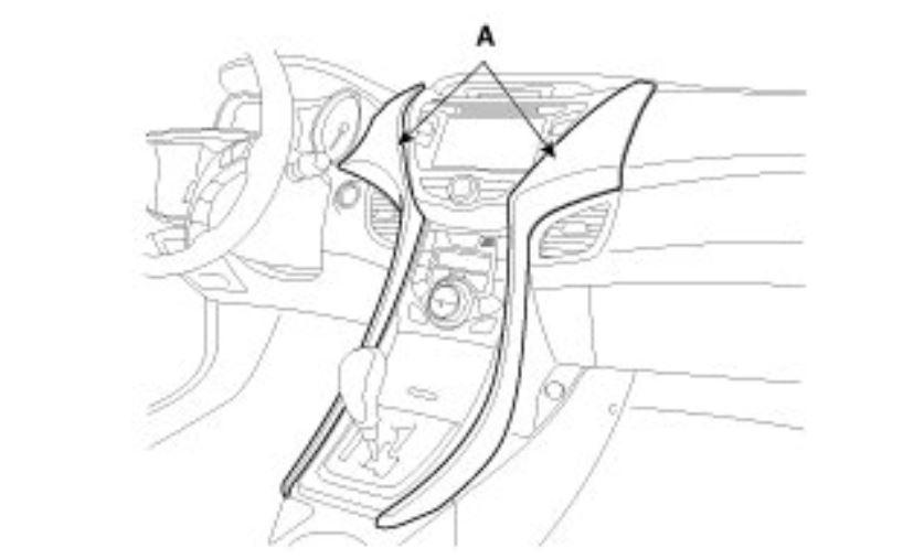
2. Using the screwdriver, remove the center garnish (A).
imageOpen In New TabZoom/Print
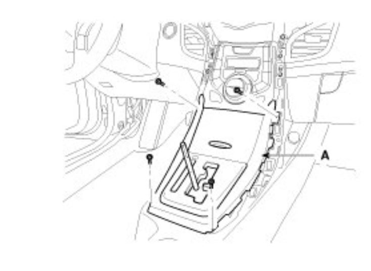
3. Loosen the mounting remove the console upper cover (A).
imageOpen In New TabZoom/Print
imageOpen In New TabZoom/Print
4. Remove the center console assembly.
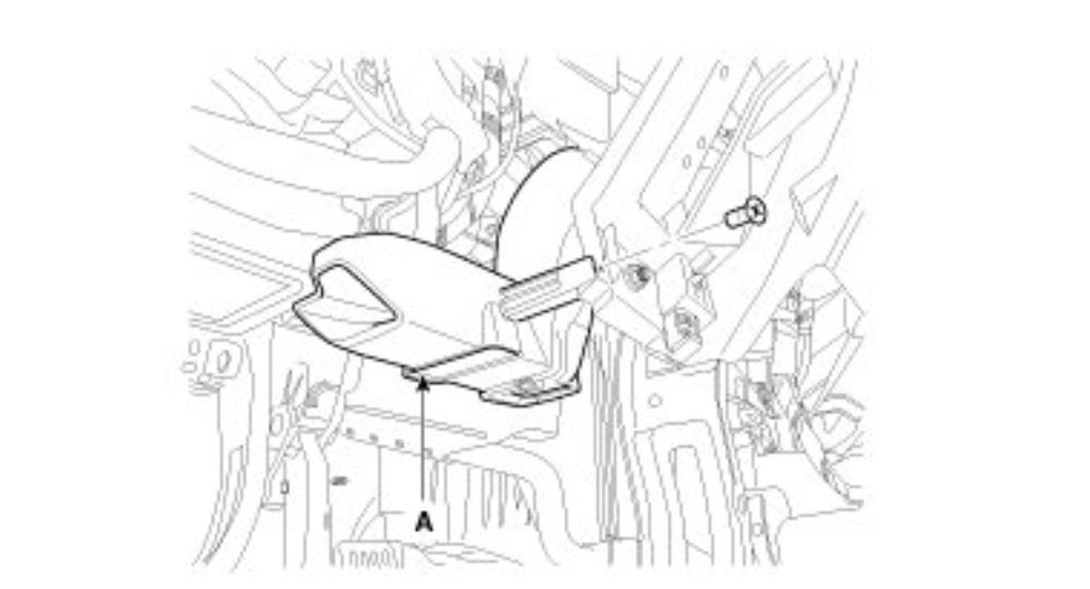
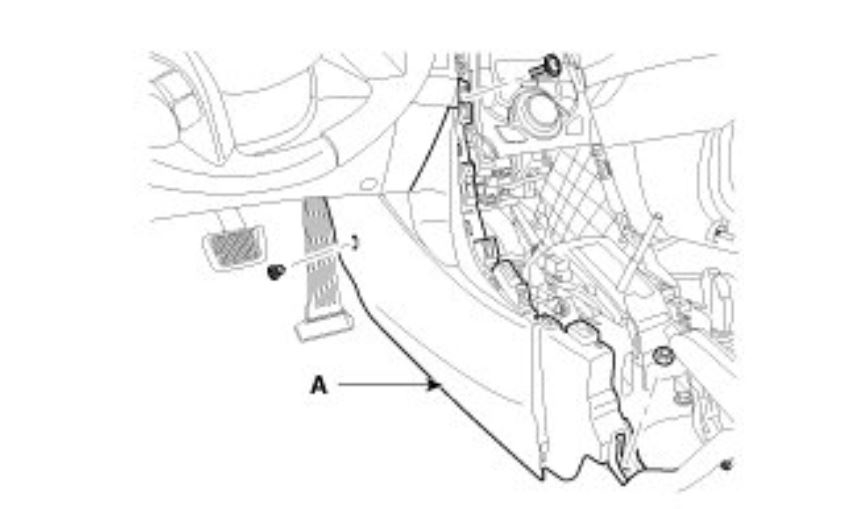
5. Loosen the mounting nut and clip remove the extension cover (A).
imageOpen In New TabZoom/Print
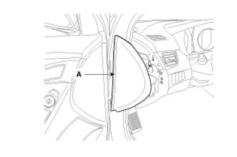
6. Remove the side cover (A).
imageOpen In New TabZoom/Print
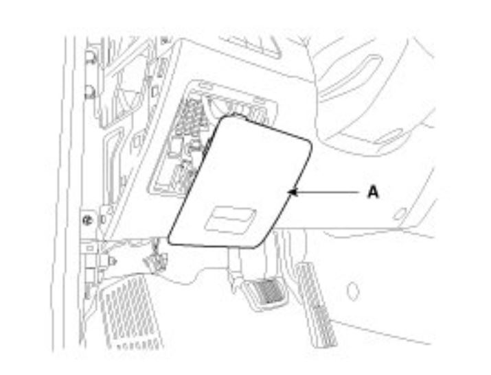
7. Disconnect the fuse box cover (A).
imageOpen In New TabZoom/Print
8. Loosen the mounting screw and then remove the crash pad lower cover (B).
imageOpen In New TabZoom/Print
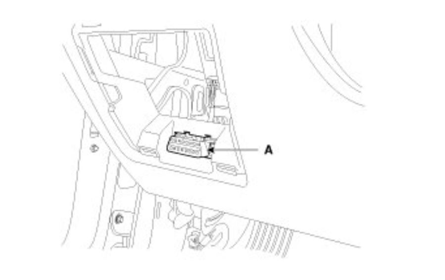
9. Disconnect the diagnosis connector (A).
imageOpen In New TabZoom/Print
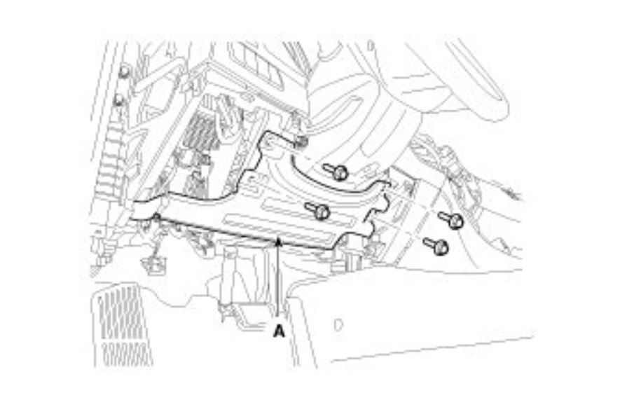
10. After loosening the mounting bolts, then remove the reinforce panel (A).
imageOpen In New TabZoom/Print
11. Remove the shower duct (A).
imageOpen In New TabZoom/Print
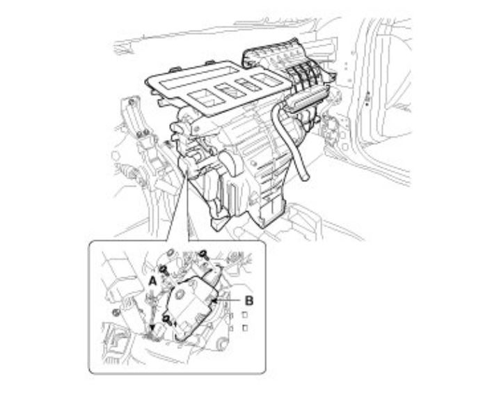
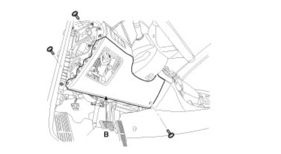
12. Disconnect the temperature control actuator connector (A)
13. Loosen the mounting screw and then remove the temperature control actuator (B).
imageOpen In New TabZoom/Print
14. Remove the side cover (A).
Images (Click to enlarge)
Jul 2, 2019 at 12:27 PM