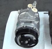
AC not taking R134a charge

Tiny
HOWARD KUEHL
  • MEMBER
  • 2003 DODGE CARAVAN
  • 3.3L
  • V6
  • FWD
  • AUTOMATIC
  • 35,000 MILES
I cannot get refrigerant to pull in and charge my system, as the compressor is not engaging completely it clicks sometimes.
I would like to test compressor by wiring a power line to positive of compressor and ground line to negative lead compressor. Then as I have heard, the clutch should activate, click and pull in to make sure it has not internal clutch short.
How can I tell which lead is positive and which is negative?
1) Can I switch those two?
2) Can I just use a nine volt battery? And do the same with the leads (either way)?
I am trying to use information in the 2003 Caravan compressor diagnosis posts as below:

Compressor clutch coil
Diagnosis and testing - compressor clutch coil:

The air conditioning compressor clutch coil electrical circuit is controlled by the power-train control module (PCM) through the compressor clutch relay, which is located in the intelligent power module (IPM) in the engine compartment near the battery. Begin testing of a suspected compressor clutch coil problem by performing the preliminary checks.

Preliminary checks:

If the compressor clutch will not engage, verify the refrigerant charge level. Refer to Refrigerant - diagnosis and testing - refrigerant charge level. If the refrigerant charge level is okay, go to step two. If the refrigerant charge level is not okay, adjust the refrigerant charge as required.
If the A/C compressor clutch still will not engage, disconnect the headlamp and dash wire harness connector for the A/C pressure transducer and check for battery current at the connector with the engine running and the heater A/C control set to the A/C mode. If okay, go to tests. If not okay, use a DRBIII (R) scan tool to perform further diagnosis. Refer to the appropriate diagnostic information.

Tests:

Verify the battery state of charge. Refer to battery - diagnosis and testing.
Connect an ammeter (0 to 10 ampere scale selected) in series with the clutch coil feed terminal. Connect a voltmeter (0 to 20 volt scale selected) to measure voltage across the battery and the clutch coil.
With the heater A/C control in the A/C mode and the blower at low speed, start the engine and allow it to run at a normal idle speed.
The compressor clutch should engage immediately, and the clutch coil voltage should be within two volts of the battery voltage. If the coil voltage is not within two volts of battery voltage, test the clutch coil feed circuit for excessive voltage drop. If the compressor clutch does not engage, use a DRBIII(R) scan tool to perform further diagnosis. Refer to the appropriate diagnostic information.
With the ambient temperature at 21 C (70 F), the compressor clutch coil is acceptable if the current draw is 2.0 to 3.7 amperes at 11.5 to 12.5 volts at the clutch coil. If the voltage is more than 12.5 volts, add electrical loads by turning on electrical accessories until the voltage reads below 12.5 volts.
If the compressor clutch coil current reading is zero, the coil is open and must be replaced.
If the compressor clutch coil current reading is four amperes or more, the coil is shorted and must be replaced.
Thursday, August 10th, 2017 AT 12:53 AM

3 Replies

Tiny
CARADIODOC
  • MECHANIC
  • 33,737 POSTS
Those tests are for people who know absolutely nothing about how the system works. You're way past that point. Those books never get opened at the dealership.

You can switch the two wires on the plug. All you're doing is creating a giant electromagnet. Polarity is not an issue. Also, the clutch is okay by your own observation. It engages occasionally. Everything you described points to a simple low-charge condition. There's two things you can do to get the compressor running. The first is to simply bypass the clutch relay, either with a jumper wire, or by installing it with its cover removed, then squeeze the movable contact. If the clutch engages, you just proved the clutch coil AND all the associated wiring and connectors are okay.

All older AC systems had a low-pressure cutout switch to disable the compressor when the system was low on charge, presumably from a leak. That was to prevent the possibility of the low side getting pumped into a vacuum. That could let air get in with the extremely harmful humidity in it. Most newer systems use a pressure-sensing switch to perform additional functions as well as the low-pressure cutout function. If you still have the low-pressure cutout switch, just unplug it, then connect the two terminals in the plug with a jumper wire. I use a stretched-out cotter pin. The compressor will run, and with the low side pressure reduced, it will be easier for the refrigerant to be drawn in.

Be aware refrigerant is extremely dangerous to work with. It can cause frost bite and blindness. Professionals wear gloves, safety glasses, AND a face shield. As more refrigerant enters the system and pressures start to rise, the compressor will cycle on for longer periods of time. Chrysler is the only manufacturer that used a sight glass on the receiver-drier that was accurate, to tell when the system is fully-charged. Add refrigerant only until you no longer see vapor bubbles flowing through that sight glass. Too much refrigerant can be more harmful than too little.
Was this
answer
helpful?
Yes
No
+1
Thursday, August 10th, 2017 AT 5:50 PM
Tiny
HOWARD KUEHL
  • MEMBER
  • 2 POSTS
Ok great, got that. I just got ground/Power probe Harbor Freight Tool Co !
I forgot that, but I had bypassed 95 Honda Civic low Pr switch before and compressor engaged.
Now I will try the Dodge.

I'm still wondering what this part means if I check relay against ground and power,
Relay terminal 30 to GRD lights the test light
86 to GRD = no light on tester
87 to POWER lights the test light
85 to POWER = no light on tester
* What does this indicate for 2003 Dodge Caravan CV 3.3L V-6
(if you can let me know)
Was this
answer
helpful?
Yes
No
Thursday, August 10th, 2017 AT 8:16 PM
Tiny
CARADIODOC
  • MECHANIC
  • 33,737 POSTS
Terminal 30 is the 12 volt feed. That will be there all the time. If it's not, there's a blown fuse.

Sorry. I thought I added this drawing before. Must have been for another AC question.

30 is connected to 87a when the relay is turned off, (not energized). That's the middle terminal on the relay on the left of my drawing, and is not used over 99 percent of the time. When the relay is energized, the movable contact switches to connect 30 to 87. At that time you'll find 12 volts on both of them and down to the clutch coil.

You actually did a slightly more advanced test by moving your test light's ground clip to the battery's positive terminal. Now it will light up when you find ground with the probe. That's what happened when you probed 87. Current went through the test light, the wire, the clutch coil, its ground wire, and back to the battery. Basically you tested and proved the clutch coil AND all the associated wiring are okay.

I dug up a wiring diagram to look at terminal 86, but that doesn't tell me everything. At first glance it shows there should be 12 volts there when the ignition switch is on, but there is "optional" circuitry listed, and that may involve a computer. You may need to have the engine running to find this 12 volts.

There won't be any voltage on 85 if there isn't on 86. 12 volts goes through the relay's coil, then appears on 85. On 85, it gets grounded by the Engine Computer when it wants to turn that relay on. Here too you fed 12 volts to the test light, then when it didn't light up, that showed the Engine Computer was not grounding that terminal. That stands to reason as it doesn't want to engage the clutch when the engine isn't running. If you leave the test light there, run the engine, and turn the AC system on, then find the test light turns on, the computer is requesting the clutch relay to turn on, and we have to figure out why there's no 12 volts on 86.
Was this
answer
helpful?
Yes
No
+1
Saturday, August 12th, 2017 AT 11:59 PM

Please login or register to post a reply.

Sponsored links