Welcome to 2CarPros.
If I recall, I believe it is 13mm or 10mm, but I could be slightly off one way or another.
If you are removing the clutch plate / hub assembly, here are the directions. You will need a puller. The attached pictures correlate with the directions.
______________________________________
AC clutch
COMPRESSOR CLUTCH PLATE/HUB ASSEMBLY REPLACEMENT (HT6/HD6/HU6)
TOOLS REQUIRED
- J 34992 Compressor Holding Fixture
- J 33013-B Hub and Drive Plate Remover/Installer
REMOVAL PROCEDURE
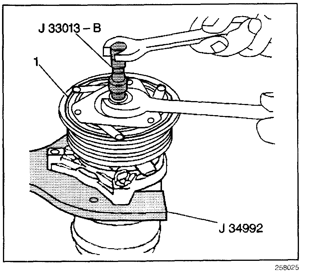
picture 1
1. Remove the A/C compressor.
2. Clamp the J 34992 in a vise.
3. Use thumb screws in order to attach the compressor to the holding fixture.
NOTE: Do not drive or pound on the clutch hub or shaft. Internal damage to the compressor may result. The forcing tip on the J 33013-B remover/installer center screw must be flat or the end of the shaft/axial plate assembly will be damaged.
4. Ensure that the center screw forces the tip to thrust against the end of the shaft.
5. Thread the J 33013-B into the hub.
6. While holding the body of J 33013-B of the remover with a wrench, turn the center screw into the remover body in order to remove the clutch plate and hub assembly (1).
7. Remove the shaft key. Retain the shaft key for reassembly.
INSTALLATION PROCEDURE
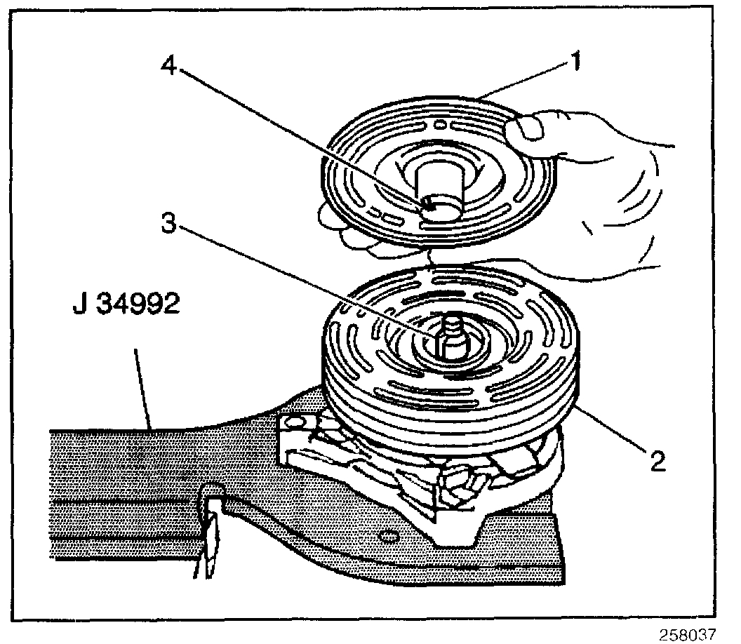
picture 2
1. Install the shaft key (4) into the hub key groove. Allow the key to project approximately 3.2 mm (0.125 in) out of the keyway (3). The shaft key curves slightly in order to provide an interference fit in the hub key groove.
2. Clean the following components:
- The clutch plate
- The clutch rotor (2)
3. Align the shaft key (4) with the shaft keyway (3).
4. Place the clutch plate and the hub assembly (1) Onto the compressor shaft.
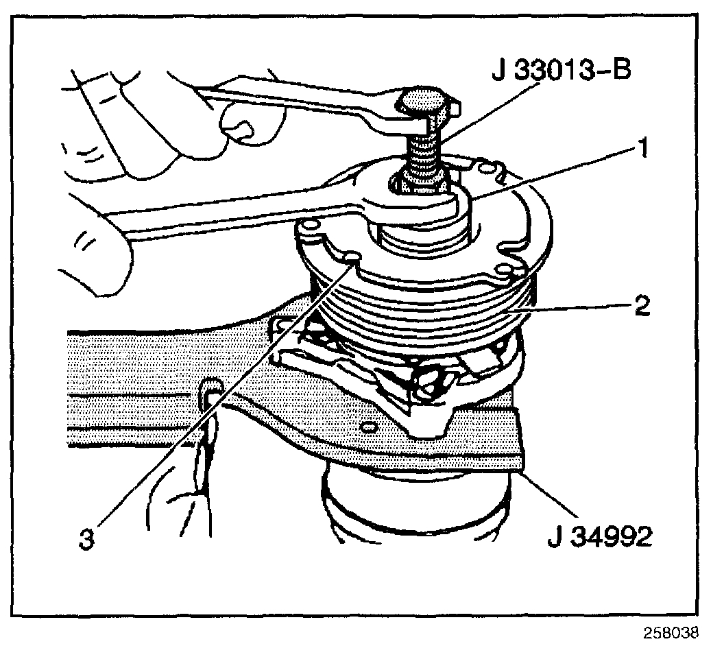
picture 3
5. Remove the forcing tip on the J 33013-B.
6. Reverse the body direction on the center screw.
7. Install the J 33013-B with the bearing.
8. Back off the body of the J 33013-B as necessary in order to permit the center screw to be threaded onto the end of the compressor shaft.
9. Hold the center screw with a wrench.
10. Tighten the hex portion of the J 33013-B body in order to press the hub onto the shaft.
11. Tighten the body several turns.
12. Remove the installer. Ensure that the shaft key remains in place in the keyway.
13. Install the clutch plate and hub assembly to the final position.
Ensure that the air gap (2) between frictional surfaces of the clutch plate and clutch rotor measures within 0.50-0.76 mm (0.020-0.030 in).
14. Remove the J 33013-B.
15. Verify proper positioning of the shaft key. Ensure that the shaft key is even with or slightly above the clutch hub.
16. Spin the pulley rotor by hand in order to verify that the rotor does not rub against the clutch drive plate.
17. Install the A/C compressor.
_____________________________
Let me know if that helps.
Take care,
Joe
Images (Click to enlarge)
Apr 29, 2019 at 7:25 PM