ABS uses the 4-wheel speed sensors to signal the ABS module about the 4 wheels rotation. The module uses them to moderate the brakes in both the traction control and ABS modes. (However, they are not the ones that send the speed signal to the display, that one is in the transaxle). In this case the code you have actually points to the ABS module as the failure -
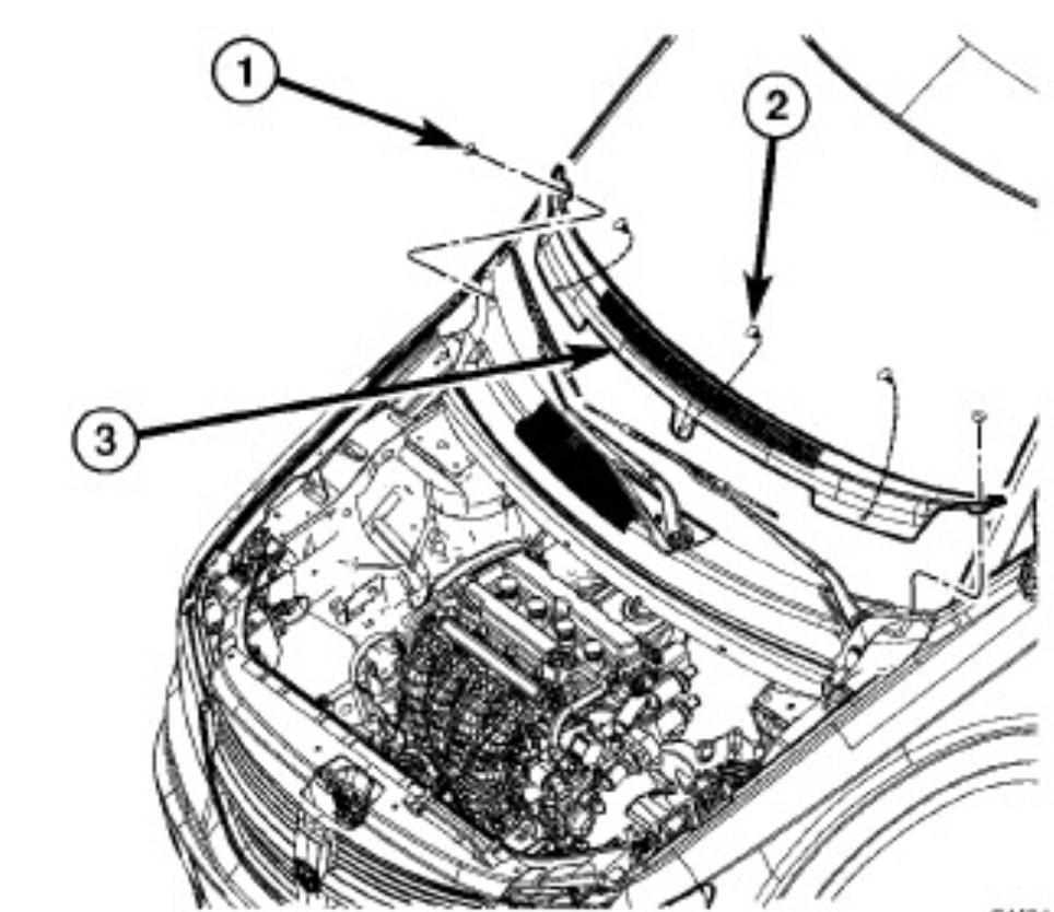
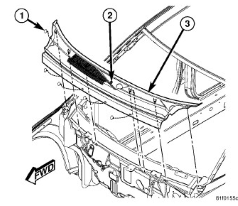
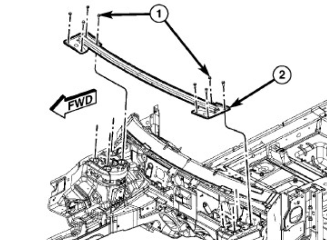
C2200-49-ANTI-LOCK BRAKE MODULE - INTERNAL ELECTRONIC FAILURE is the module itself shows an internal error and has shut off, in turn it turns on the ABS and traction lights as both systems use that module. The first thing is write that code down, then use a scan tool to erase it. If it is a hard fault the light will come back almost instantly. The module can be replaced without removing the brake lines but it isn't a fun repair due to the location of the module where it is buried back under the cowl. I generally don't short cut this one because it's a tight fit. That starts with removing the cowl panel and support to get room to work on it easier than through the gap. You start by removing the top cowl trim and the wiper arms. The arms use a nut to secure them to the wiper transmission, The trim caps lift up and then you hold the arm and remove the nut. If they stick a quick hit with your hand on the hinge point will usually pop them off the taper. Now you remove the push pins that secure the lower cowl screen. Then finally you remove the cowl brace bolts and set it aside.
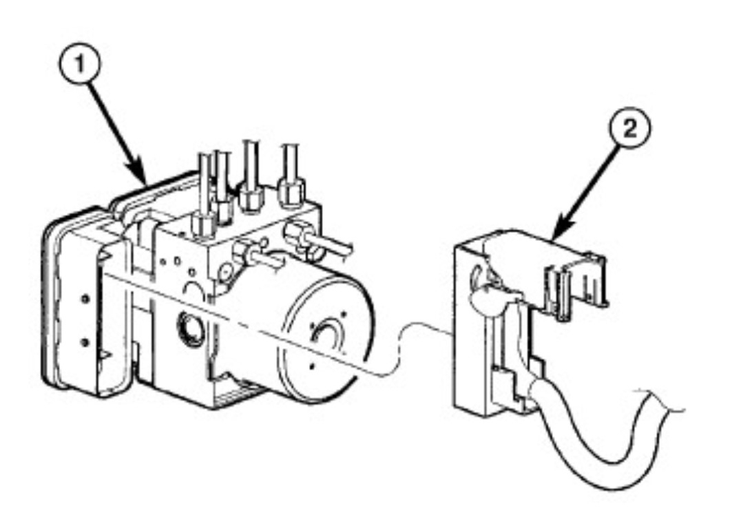
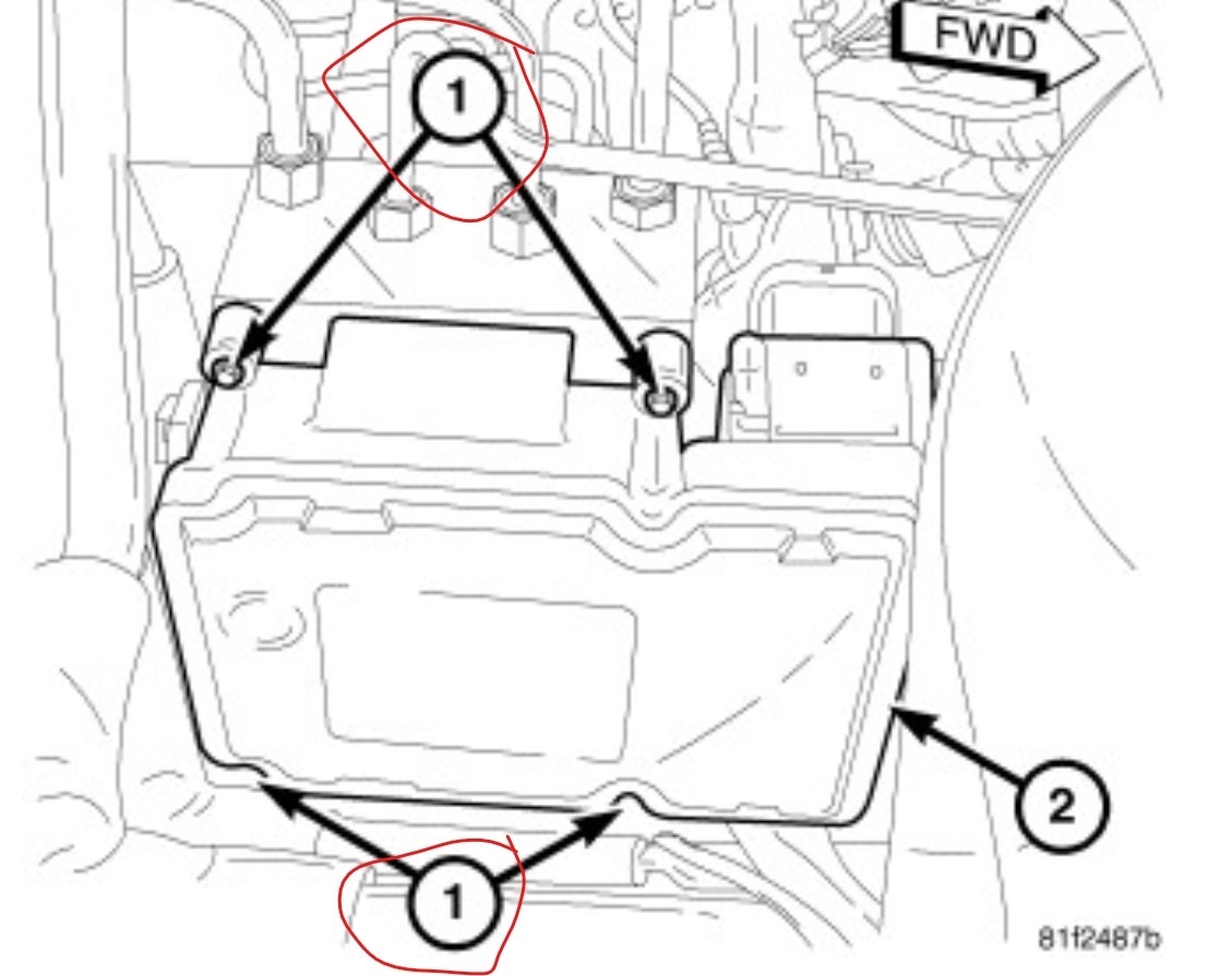
Lastly remove the air duct that comes around that area. Now with that out of the way you have more room to work. The first thing to do is clean the module and around it, I generally blow the area off then spray it with brake cleaner and hit it again with the air. There are 2 bolts in slots that hold the ABS unit to the chassis. The book says just loosen them and slide the unit up, instead you will want to remove them as it's easier. Then you move the unit enough that there are a couple inches of room between the module and the chassis. Then disconnect the battery negative, then the large connector on the module. Next, check that the area is clean again, then remove the 4 torx 20 screws that secure the module to the hydraulic unit. Pull the module straight back off the hydraulic unit. Now reverse the process to install the new part and work back to the beginning. Be sure that all the seals are in place as you install the unit.
NOW - once you have the unit all in place you need to use the scan tool to initialize the replacement module. Then you use the scan to verify the repair.
Images (Click to enlarge)
Jul 26, 2025 at 10:18 AM