Hi and thanks for using 2CarPros.com.
First, here is a link that discusses how to check for no heat problems and how to fix.
https://www..com/articles/car-heater-not-working
This can be the result of a few things. First, with the engine running at operating temperature, the heater on high, feel both heater core hoses under hood at the firewall. Both should be hot. If one is hot and the other not, suspect the heater core is plugged or low coolant.
If both are hot, then suspect the blend air door actuators are not working. I believe this vehicle has duel climate control, meaning separate temperatures can be selected by the driver and passenger. With that in mind, it is not common for both left and right actuators to go bad at the same time. However, if the heater core hoses are both hot, that tells me the heater core is hot and the only thing that can be stopping heat from entering the vehicle are these blend air doors.
If you determine the actuators are the problem, here are the directions for replacing them. The directions are broken down into two parts, left and right. I will start with the right. All attached pictures will correlate with the directions.
__________________________________________
IR TEMPERATURE ACTUATOR REPLACEMENT - RIGHT
REMOVAL PROCEDURE
1. Remove the instrument panel compartment.
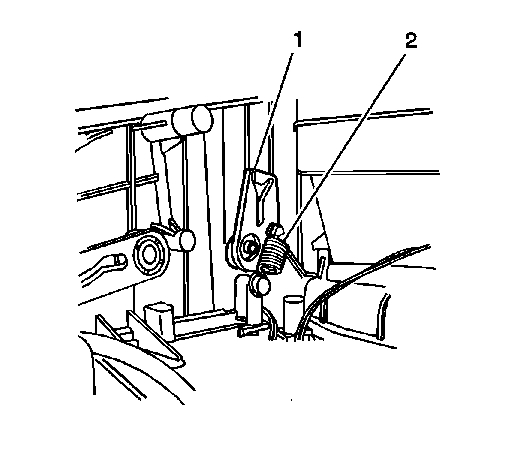
2. Disconnect and remove the right hand temperature door lever spring (2).
3. Disconnect and remove the right hand temperature lever (1) from the right hand temperature door.
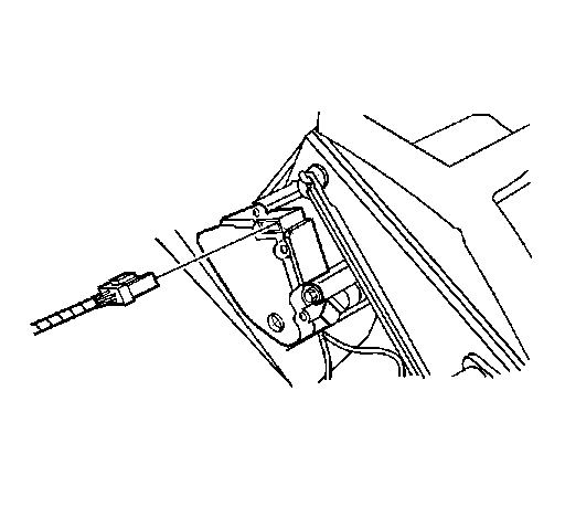
4. Disconnect the right hand temperature actuator electrical connector.
5. Remove the right hand temperature actuator mounting screws.
6. Remove the right hand temperature actuator.
INSTALLATION PROCEDURE
1. Install the right hand temperature actuator.
2. Install the right hand temperature actuator mounting screws.
Tighten the screws to 1.6 N.m (14 lb in).
NOTE: Refer to Fastener Notice in Service Precautions.
3. Connect the right hand temperature actuator electrical connector.
4. Install the right hand temperature lever (1) to the right hand temperature door.
IMPORTANT: Align the pin on the right hand air temperature actuator with the slot in the right hand temperature door lever.
5. Connect the right hand temperature door lever spring (2) to the right hand temperature door lever (1) and HVAC module case.
6. Install the instrument panel compartment.
___________________________________
Left
AIR TEMPERATURE ACTUATOR - LEFT
AIR TEMPERATURE ACTUATOR REPLACEMENT - LEFT
REMOVAL PROCEDURE
1. Remove the knee bolster.
2. Set the HVAC controls to the vent mode to position the defroster door lever.
IMPORTANT: The HVAC controls must be set to the vent mode to position the defroster door lever for access to the air temperature actuator.
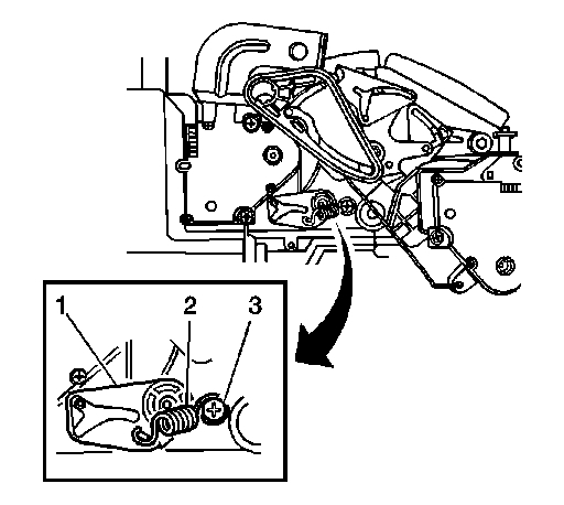
3. Remove the left hand temperature door lever bolt (3) from the HVAC module.
4. Disconnect and remove the left hand temperature door lever spring (2).
5. Disconnect and remove the left hand temperature door lever (1) from the left hand temperature door.
6. Disconnect the left hand air temperature actuator electrical connector.
7. Remove the left hand air temperature actuator mounting screws.
8. Remove the left hand air temperature actuator.
INSTALLATION PROCEDURE
1. Install the left hand air temperature actuator.
2. Install the left hand air temperature actuator mounting screws.
Tighten the screws to 1.6 N.m (14 lb in).
NOTE: Refer to Fastener Notice in Service Precautions.
3. Connect the left hand air temperature actuator electrical connector.
4. Install the left hand temperature door lever (1) to the left hand temperature door.
IMPORTANT: Align the pin on the left hand air temperature actuator with the slot in the left hand temperature door lever.
5. Connect the left hand temperature door lever spring (2) to the left hand temperature door lever (1) and HVAC module case.
6. Install the left hand temperature door lever bolt (3) to the HVAC module case.
Tighten the bolt to 0.9 N.m (8 lb in).
7. Install the knee bolster.
________________________________
Let me know if this helps or if you have other questions.
Take care,
Joe
Images (Click to enlarge)
Nov 14, 2018 at 7:32 PM