Using scan tool, read FREEZE FRAME data. Freeze frame data records engine conditions when malfunction is detected.
Diagnosis & Repair
1. Check for spark at misfiring cylinder. See IGNITION SYSTEMS in BASIC DIAGNOSTIC PROCEDURES 4 CYLINDER article. If spark exists, go to next step. If spark does not exist, go to step 4.
2. Check for open or short in Blue/Yellow wire between ECM and ignition coil/ignitor No. 3. Also, check for open or short in Gray wire between ECM and ignition coil/ignitor No. 3. See WIRING DIAGRAMS
article. If problem exists, repair wiring as necessary. If problem does not exist, go to next step.
3. Disconnect ignition coil/ignitor No. 3 harness connector. Access ECM below stereo, behind instrument panel, just in front of center console. See Fig. 2. Turn ignition on. Using DVOM, backprobe at ECM
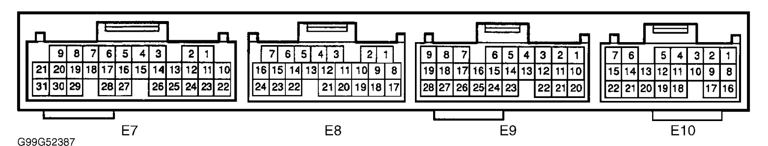
harness connector. On models with 4A/T transmission, measure voltage between ground and terminal No. 25 (Blue/Yellow wire) at ECM harness connector E7. See Fig. 4. On models without 4A/T transmission,
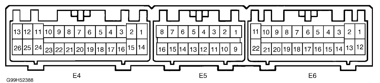
measure voltage between ground and terminal No. 3 (Blue/Yellow wire) at ECM harness connector E4. See Fig. 5. On all models, voltage should be 4.5 5.5 volts. If voltage is as specified, replace ignition
coil/ignitor No. 3. If voltage is not as specified, replace ECM.
4. Check for open or short in Gray wire between ECM and ignition coil/ignitor No. 3. See WIRING DIAGRAMS article. If problem exists, repair wiring as necessary. If problem does not exist, go to next step.
5. Access ECM below stereo, behind instrument panel, just in front of center console. See Fig. 2. Using DVOM, backprobe ECM harness connector. On models with 4A/T transmission, measure voltage between
ground and terminal No. 12 (Gray wire) at ECM harness connector E7 while cranking engine. See Fig. 4. On models without 4A/T transmission, measure voltage between ground and terminal No. 22 (Gray wire)
at ECM harness connector E4 while cranking engine. See Fig. 5. On all models, voltage should be .1 4.5 volts. If voltage is not as specified, go to next step. If voltage is as specified, go to step 7.
6. Disconnect ignition coil/ignitor No. 3 harness connector. Using DVOM, backprobe ECM harness connector. On models with 4A/T transmission, measure voltage between ground and terminal No. 12 (Gray wire)
at ECM harness connector E7 while cranking engine. On models without 4A/T transmission, measure voltage between ground and terminal No. 22 (Gray wire) at ECM harness connector E4 while cranking
Images (Click to enlarge)
Jan 10, 2012 at 5:37 PM