Yes, this is most likely control rather than mechanical.
DTC P1885/34: DRIVE PULLEY SPEED SENSOR/CIRCUIT
1. Using scan tool, retrieve A/T freeze data. Clear DTCs and road test vehicle under same conditions freeze data was recorded. If DTC returns, go to next step. If DTC does not return, problem is intermittent. Check transaxle and PCM connections.
2. Turn ignition on. Using scan tool, check for TP sensor DTCs (P0122, P0123, P1121 or P1122). If any TP sensor DTCs are present, repair those DTCs first. If no TP sensor DTCs are present, go to next step.
3. Turn ignition off. Disconnect drive pulley speed sensor harness connector. Turn ignition on. Measure voltage between ground and drive pulley speed sensor harness connector terminal No. 1 (Yellow/Blue wire). If voltage is about 5 volts, go to next step. If voltage is not about 5 volts, go to step 9 .
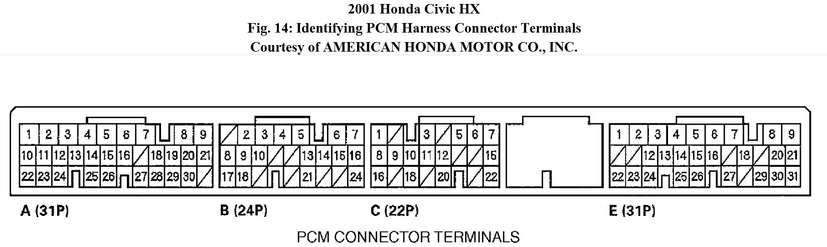
4. Turn ignition off. Disconnect PCM harness connector "C". Check continuity between ground and drive pulley speed sensor harness connector terminal No. 2 (Red/Blue wire). If continuity does not exist, go to next step. If continuity exists, repair short to ground in Red/Blue wire between PCM harness connector "C" and drive pulley speed sensor.
5. Check continuity between ground and drive pulley speed sensor harness connector terminal No. 3 (Brown/Yellow wire). If continuity exists, go to next step. If continuity does not exist, repair loose connector or open in Brown/Yellow wire between drive pulley speed sensor harness connector terminal No. 3 and ground, or repair poor ground connection.
6. Reconnect PCM harness connector "C". Turn ignition on. Measure voltage between drive pulley speed sensor harness connector terminals No. 2 and 3 (Red/Blue wire and Brown/Yellow wire). If voltage is about 5 volts, go to step 12. If voltage is not about 5 volts, go to next step.
7. Measure voltage between terminal No. 7 on PCM harness connector "C" and terminals No. 23 or 24 on PCM harness connector "A". If voltage is not about 5 volts, go to next step. If voltage is about 5 volts, repair open in Red/Blue wire between PCM harness connector "C" and drive pulley speed sensor harness
connector.
8. Reprogram PCM if it does not have the latest software, or substitute a known-good PCM, then recheck. If malfunction goes away with a known-good PCM, replace original PCM.
9. Measure voltage between ground and terminal No. 20 on PCM harness connector "A". If 4.75-5.25 volts is not present, go to next step. If 4.75-5.25 volts is present, repair open in Yellow/Blue wire between PCM harness connector "A" and drive pulley speed sensor harness connector.
10. Turn ignition off. Disconnect PCM harness connector "C". Check continuity between ground and terminal No. 20 on PCM harness connector "A". If continuity does not exist, go to next step. If continuity exists, repair short to ground in Yellow/Blue wire between PCM harness connector "C" and drive pulley speed sensor harness connector.
11. Reprogram PCM if it does not have the latest software, or substitute a known-good PCM, then recheck. If malfunction goes away with a known-good PCM, replace original PCM.
12. Reconnect drive pulley speed sensor harness connector. Measure voltage between terminal No. 7 on PCM harness connector "C" and terminals No. 23 or 24 on PCM harness connector "A". If voltage is about 0-5 volts, go to next step. If voltage is not about 0-5 volts, replace drive pulley speed sensor.
13. Ensure all components are reconnected. Raise and support front of vehicle. Apply parking brake and block rear wheels. Start engine, then shift gearshift lever to "D" position. With front wheels rotating, measure voltage between terminal No. 7 on PCM harness connector "C" and terminals No. 23 or 24 on PCM harness connector "A". If voltage is 1.5-3.5 volts, go to next step. If voltage is not 1.5-3.5 volts, replace drive pulley speed sensor.
14. Reprogram PCM if it does not have the latest software, or substitute a known-good PCM, then recheck. If malfunction goes away with a known-good PCM, replace original PCM.
Sep 8, 2012 at 6:11 PM