The code's i would be most concern with is your transmission code's if left alone they could cause internal transmission damage.Your o2 sensor is the least of your worries.Your transmission code's are P1811 which i posted that bulletin.Code p0742 * Rapid fluctuation in line pressure could set DTC P0742.
* Inspect for a pressure regulator problem.
* Inspect for abnormal line pressure.
* Inspect the wiring for poor electrical connections at the PCM. Inspect the wiring for poor electrical connections at the transmission 20-way connector. Look for the following problems:
* A bent terminal
* A backed out terminal
* A damaged terminal
* Poor terminal tension
* A chafed wire
* Moisture Intrusion
* A broken wire inside the insulation
* When diagnosing for an intermittent short or open, massage the wiring harness while watching the test equipment for a change.
* The customer may notice an engine stalling problem.
Now your other codes P1107
CIRCUIT DESCRIPTION
The Manifold Absolute Pressure (MAP) sensor responds to changes in intake manifold pressure (vacuum). The MAP sensor signal voltage to the PCM varies from below 2 volts at idle (high vacuum) to above 4 volts with the key ON, engine not running or at wide-open throttle (low vacuum). The MAP sensor is used to determine manifold pressure changes while the linear EGR flow test diagnostic is being run (refer to DTC P0401), to determine engine vacuum level for some other diagnostics and to determine barometric pressure (BARO). The PCM monitors the MAP signal for voltages outside the normal range of the MAP sensor. If the PCM detects a MAP signal voltage that is intermittently low, DTC P1107 will be set.
CONDITIONS FOR RUNNING THE DTC
1. No Throttle Position (TP) sensor DTC(s) are present.
2. The ignition is ON.
3. Throttle angle is steady above 10% if engine speed is greater than 1000 rpm.
CONDITIONS FOR SETTING THE DTC
1. The MAP sensor intermittently indicates a manifold absolute pressure below 0.1 volt.
ACTION TAKEN WHEN THE DTC SETS
* The PCM will not illuminate the Malfunction Indicator Lamp (MIL).
* The PCM will store conditions which were present when the DTC set as Fail Records data only. This information will not be stored as Freeze Frame data.
CONDITIONS FOR CLEARING THE MIL/DTC
* A history DTC will clear after 40 consecutive warm-up cycles have occurred without a malfunction.
* DTC can be cleared by using the scan tool Clear Info function or by disconnecting the PCM battery feed.
DIAGNOSTIC AIDS
Check for the following conditions:
1. Poor connection at PCM or MAP sensor.
Inspect PCM harness connectors for backed out terminals, improper mating, broken locks, improperly formed or damaged terminals, and poor terminal to wire connection.
2. Damaged harness.
Inspect the wiring harness for damage. If the harness appears to be OK, observe the MAP display on the scan tool while moving connectors and wiring harnesses related to the sensor. A change in the display will indicate the location of the malfunction.
Reviewing the Fail Records vehicle mileage since the diagnostic test last failed may help determine how often the condition that caused the DTC to be set occurs. This may assist in diagnosing the condition.
P0135
CIRCUIT DESCRIPTION
Heated oxygen sensors are used to minimize the amount of time required for closed loop fuel control operation and to allow accurate catalyst monitoring. The oxygen sensor heater greatly decreases the amount of time required for fuel control sensor HO2S 1 to become active. The oxygen sensor heater is required by catalyst monitor sensor HO2S 2 to maintain a sufficiently high temperature. This allows accurate exhaust oxygen content readings further from the engine.
The PCM will run the heater test only after a cold start (determined by engine coolant and intake air temperature at the time of start-up) and only once during an ignition cycle. When the engine is started the PCM will monitor the HO2S voltage. When the HO2S voltage indicates a sufficiently active sensor, the PCM looks at how much time has elapsed since start-up. If the PCM determines that too much time was required for the HO2S 1 to become active, a DTC P0135 will set. The time it should take the HO2S to reach operating temperature is based on the engine coolant temperature at start-up and the average Mass Air Flow since start-up (higher average airflow or higher start-up engine coolant temperature = shorter time to HO2S activity).
CONDITIONS FOR RUNNING THE DTC
* No Throttle Position (TP) sensor, EVAP system, misfire, Intake Air Temperature (IAT) sensor, Manifold Absolute Pressure (MAP) sensor, fuel trim, fuel injector circuit, EGR Pintle Position, Engine Coolant Temperature (ECT) sensor, Crankshaft Position (CKP) sensor, or Mass Air Flow (MAF) sensor DTC(s) are present.
* System voltage is between 9 and 16 volts.
* Intake Air Temperature (IAT) is less than 35°C (95°F) at start-up.
* Engine Coolant Temperature (ECT) is less than 35°C (95°F) at start-up.
* IAT and Engine Coolant Temperature (ECT) are within 6°C (11°F) of each other at start-up.
* VIN K - Average mass airflow for the sample period is less than 18 g/s.
VIN 1 - Average mass airflow for the sample period is less than 19 g/s.
CONDITIONS FOR SETTING THE DTC
HO2S 1 voltage remains within 150 mV of the bias voltage (about 450 mV) for a longer amount of time than it should. The amount of time ranges between 50 and 80 seconds depending on engine coolant temperature at start-up and average Mass Air Flow since start-up.
ACTION TAKEN WHEN THE DTC SETS
* The PCM will illuminate the MIL during the second consecutive trip in which the diagnostic test has been run and failed.
* The PCM will store conditions which were present when the DTC set as Freeze Frame and Fail Records data.
CONDITIONS FOR CLEARING THE MIL/DTC
* The PCM will turn the MIL OFF during the third consecutive trip in which the diagnostic has been run and passed.
* The history DTC will clear after 40 consecutive warm-up cycles have occurred without a malfunction.
* The DTC can be cleared by using the scan tool Clear Info function or by disconnecting the PCM battery feed.
DIAGNOSTIC AIDS
Check for the following conditions:
* Poor connections at the PCM. Inspect harness connectors for backed out terminals, improper mating, broken locks, improperly formed or damaged terminals, and poor terminal to wire connection.
* Damaged harness. Inspect the wiring harness for damage.
* If the harness appears to be OK, observe the display on the scan tool while moving connectors and wiring harnesses related to the sensor. A change in the display will indicate the location of the malfunction.
Reviewing the Fail Records vehicle mileage since the diagnostic test last failed may help determine how often the condition that caused the DTC to be set occurs. This may assist in diagnosing the condition.
TEST DESCRIPTION
Number(s) below refer to the step number(s) on the Diagnostic Table.
2. The HO2S should be allowed to cool before performing this test. If the HO2S heater is functioning, the signal voltage will gradually increase or decrease as the sensor element warms. If the heater is not functioning, the HO2S signal will remain near the 450mv bias voltage.
4. Ensures that the ignition feed circuit to the HO2S is not open or shorted. The test light should be connected to a good chassis ground in case the HO2S low or HO2S heater ground circuit is malfunctioning.
5. Checks the HO2S heater ground circuit.
6. Checks for an open or shorted HO2S heater element.
IMPORTANT: The heater element resistance will vary according to HO2S temperature (a hot HO2S heater element will measure a much higher resistance than a HO2S heater element at room temperature). Allow the HO2S to cool before measuring HO2S heater element resistance.
11. An open HO2S signal or low circuit can cause the DTC to set with the HO2S heater operating normally. Check the HO2S signal and the HO2S low circuits before replacing the sensor.
P0133
CIRCUIT DESCRIPTION
The PCM continuously monitors the Heated Oxygen Sensor (HO2S) activity for 100 seconds. During the monitoring period the PCM counts the number of times that the a rich to lean and lean to rich response is indicated and adds the amount of time it took to complete all transitions. With this information, an average time for each transition can be determined. If the average response time is too slow, a DTC P0133 will be set. A lean to rich transition is indicated when the HO2S voltage changes from less than 300 mV to greater than 600 mV. A rich to lean transition is indicated when the HO2S voltage changes from more than 600 mV to less than 300 mV. An HO2S that responds too slowly is likely to be malfunctioning and should be replaced.
CONDITIONS FOR RUNNING THE DTC
* No Throttle Position (TP) sensor, EVAP system, misfire, Intake Air Temperature (IAT) sensor, Manifold Absolute Pressure (MAP) sensor, fuel trim, fuel injector circuit, EGR Pintle Position, Engine Coolant Temperature (ECT) sensor, HO2S heater circuit sensor 1, Crankshaft Position (CKP) , or Mass Air Flow (MAF) sensor DTC(s) present
* Engine has been running in Closed Loop fuel control for at least 60 seconds.
* Engine speed is between 1000 RPM and 3000 RPM.
* Engine Coolant Temperature greater than 50°C (122°F).
* Mass Air Flow between 10 g/s and 30 g/s.
CONDITIONS FOR SETTING THE DTC
VIN K - HO2S 1 lean to rich average transition response time during the sample period was longer than 140 milliseconds or rich to lean average transition response time during the sample period was longer than 107 milliseconds.
VIN 1 - HO2S 1 lean to rich average transition response time during the sample period was longer than 130 milliseconds or rich to lean average transition response time during the sample period was longer than 110 milliseconds.
ACTION TAKEN WHEN THE DTC SETS
* The PCM will illuminate the MIL during the second consecutive trip in which the diagnostic test has been run and failed.
* The PCM will store conditions which were present when the DTC set as Freeze Frame and Fail Records data.
CONDITIONS FOR CLEARING THE MIL/DTC
* The PCM will turn the MIL OFF during the third consecutive trip in which the diagnostic has been run and passed.
* The history DTC will clear after 40 consecutive warm-up cycles have occurred without a malfunction.
* The DTC can be cleared by using the scan tool Clear Info function or by disconnecting the PCM battery feed.
DIAGNOSTIC AIDS
Check for the following conditions:
* Poor Connections at PCM. Inspect harness connectors for backed out terminals, improper mating, broken locks, improperly formed or damaged terminals, and poor terminal to wire connection.
* Damaged harness. Inspect the wiring harness for damage. If the harness appears to be OK, observe the HO2S 1 display on the scan tool while moving connectors and wiring harnesses related to the sensor. A change in the display will indicate the location of the malfunction. If DTC P0133 cannot be duplicated, Reviewing the Fail Records vehicle mileage since the diagnostic test last failed may help determine how often the condition that caused the DTC to be set occurs. This may assist in diagnosing the condition.
TEST DESCRIPTION
Number(s) below refer to the step number(s) on the Diagnostic Table:
2. Verifies that the malfunction is currently present.
3. HO2S transition time, ratio, and switching DTCs set for multiple sensors indicate probable contamination. Before replacing the sensors, isolate and correct the source of the contamination to avoid damaging the replacement sensors.
Can't find your P010 it's missing a number the should be a letter then 4 number's.
Your code P1626
CIRCUIT DESCRIPTION
The Vehicle Theft Deterrent (VTD) module is located within the steering column. The VTD system prevents the vehicle from cranking and starting if a valid ignition key signal is not received by the VTD module. Once the proper ignition key signal is received by the VTD module, a continue fuel enable password is sent to the PCM via class 2 serial data. The PCM monitors the state of health serial data message from the theft deterrent system to ensure that the PCM - VTD module communications is established. If the PCM detects a loss of the state of health message while the engine is running, DTC P1626 will be set. DTC P1626 can cause a no-start condition or normal operation depending on when the loss of system communication was detected. The engine will continue to start and run if the condition that set DTC P1626 occurred after the PCM received a valid VTD password from the VTD module and already allowed fuel during the ignition cycle. The engine will not start or crank if the condition that set DTC P1626 occurred before the PCM received a valid VTD password. With this condition present, the PCM will inhibit fuel delivery and disable the starter until a valid VTD password is detected.
CONDITIONS FOR SETTING THE DTC
* The VTD system has allowed fuel delivery.
* The PCM has detected a loss of the state of health serial data message from the VTD system.
ACTION TAKEN WHEN THE DTC SETS
* The PCM will not illuminate the Malfunction Indicator Lamp (MIL).
* The PCM will store conditions which were present when the DTC set as Fail Records data only. This information will not be stored as Freeze Frame data.
CONDITIONS FOR CLEARING THE MIL/DTC
* A history DTC will clear after 40 consecutive warm-up cycles have occurred without a malfunction.
* DTC can be cleared by using the scan tool Clear Info function or by disconnecting the PCM battery feed.
DIAGNOSTIC AIDS
For complete serial data line schematics and VTD system diagnosis, refer to Electrical Diagnosis. An intermittent may be caused by a poor connection, rubbed through wire insulation or a wire broken inside the insulation. Check for:
IMPORTANT: Several VTD system diagnostic procedures may call for disconnecting the VTD module and then turning the vehicle ignition to the RUN position. These procedures will result in the PCM setting DTC P1626. Therefore, DTC P1626 stored in history may be the result of previous diagnostic work.
* Intermittent short circuit on the serial data circuit. Refer to Data Link Connector (DLC) System Check in Electrical Diagnosis and check all related wiring for an intermittent short to ground or short to voltage.
* Poor Connection. Inspect the PCM and VTD module harness and related connectors for improper mating, broken locks, improperly formed or damaged terminals, and poor terminal to wire connection.
* Damaged harness. Inspect the wiring harness for damage. Check for an intermittent short or open circuit in the wiring harnesses related to the VTD module, including the ignition, battery feed, ground, and serial data circuits. Refer to troubleshooting procedures in Electrical Diagnosis.
Reviewing the Fail Records vehicle mileage since the diagnostic test last failed may help determine how often the condition that caused the DTC to be set occurs. This may assist in diagnosing the condition.
Your code P1671
CIRCUIT DESCRIPTION
Output Driver Modules (ODMs) are used by the PCM to turn on many of the current-driven devices that are needed to control various engine and Transaxle functions. Each ODM is capable of controlling up to 7 separate outputs by applying ground to the device which the PCM is commanding ON. Unlike the Quad Driver Modules (QDMs) used in prior model years, ODMs have the capability of diagnosing each output circuit individually. DTC P1671 set indicates an improper voltage level on the output circuit that controls the Malfunction Indicator Lamp (MIL) .
CONDITIONS FOR SETTING THE DTC
* Ignition is ON.
* An improper voltage level has been detected on the output circuit for the MIL control.
* Above conditions for at least 36 seconds.
ACTION TAKEN WHEN THE DTC SETS
* The PCM will not illuminate the Malfunction Indicator Lamp (MIL).
* The PCM will store conditions which were present when the DTC set as Fail Records data only. This information will not be stored as Freeze Frame data.
CONDITIONS FOR CLEARING THE MIL/DTC
* A history DTC will clear after 40 consecutive warm-up cycles have occurred without a malfunction.
* DTC can be cleared by using the scan tool Clear Info function or by disconnecting the PCM battery feed.
DIAGNOSTIC AIDS
Check for the following conditions:
* Poor connection at the PCM.
Inspect harness connectors for backed out terminals, improper mating, broken locks, improperly formed or damaged terminals, and poor terminal to wire connection.
* Damaged harness.
Inspect the wiring harness for damage. If the harness appears to be OK, disconnect the PCM, turn the ignition ON and observe a digital multimeter connected between the MIL control circuit and ground at the PCM harness connector while moving connectors and wiring harnesses related to the MIL. A change in voltage will indicate the location of the malfunction.
Reviewing the Fail Records vehicle mileage since the diagnostic test last failed may help determine how often the condition that caused the DTC to be set occurs. This may assist in diagnosing the condition.
TEST DESCRIPTION
Number(s) below refer to the step number(s) on the Diagnostic Table.
2. Normally, ignition feed voltage should be present on the control circuit with the PCM disconnected and the ignition turned ON.
3. Checks for a shorted component or a short to B+ on the control circuit. Either condition would result in a measured current of over 500 milliamps. Also checks for a component that is causing an open circuit while being operated, resulting in a measured current of 0 milliamps.
4. Checks for a short to voltage on the control circuit.
14. This vehicle is equipped with a PCM which utilizes an Electrically Erasable Programmable Read Only Memory (EEPROM) . When the PCM is being replaced, the new PCM must be programmed
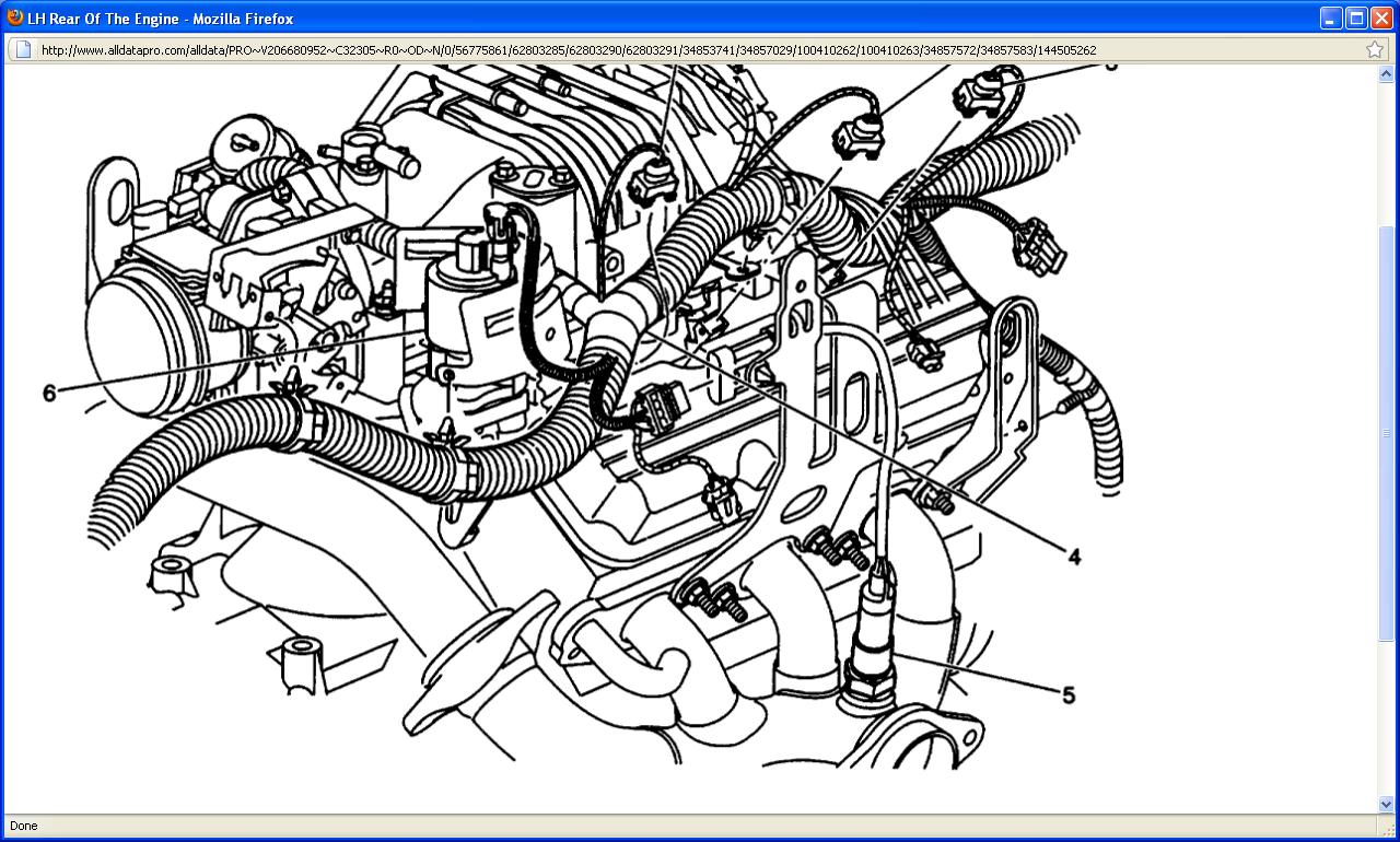
I posted a diagram of where your o2 sensor is that there is a code for its number 5 in the diagram.As far as your pressure control solenoid its 4.6 hrs they charge to change it plus fluid and and filter say 100 to safe on that.Plus 100 on the solenoid to be safe.As far as replacing the solenoid yourself if your good at working on car's i would say you could.It's a big job you have to remove the side cover of the transmission or at least move it aside enough to replace the solenoid.You still have to perform a pressure test before changing that pressure control solenoid.Your code P0742 could possible be caused by a pressure issue.If your read the code description i posted it says that.There is no easy fix for your car i would work on the transmission code's first.
Mar 2, 2011 at 7:17 PM