Read this carefully
DTC P0172 - FUEL TRIM SYSTEM RICH BANK 1
Circuit Description PCM monitors oxygen sensor signal voltage and adjusts fuel delivery based on signal voltage. A change made to fuel delivery is indicated by the long and short term fuel trim values.
Short term fuel trim values change rapidly in response to HO2S signal voltages. These changes fine tune engine fueling. Long term fuel trim values changes in response to trends in short term fuel trim. Long term fuel trim makes coarse adjustments to fueling in order to re-center and restore control to short term fuel trim. Long term and short term fuel trim can be monitored by use of scan tool.
Ideal fuel trim value is about zero percent. A positive fuel trim indicates that PCM is adding fuel to compensate for a lean condition. A negative fuel trim indicates that PCM is reducing amount of fuel to compensate for rich condition. DTC will set if PCM detects an excessively rich or lean condition.
Diagnostic Procedures Perform On-Board Diagnostic (OBD) System Check. After performing OBD system check, go to next step.
NOTE:If other DTC(s) are present, except P0175, diagnose affected DTC(s) first.
Start and warm engine to normal operating temperature. Ensure system is in "closed loop" operation. Using scan tool, select FUEL TRIM DATA LIST and monitor LT FT AVG. BN 1 and ST FT AVG. BN 1 values. If LT FT AVG. Is greater than -14 percent and ST FT AVG. Reads greater than -10 percent, go to next step. If not greater than specification, go to step 4).
Turn ignition on, with engine off. Using scan tool, review FREEZE FRAME and/or FAILURE RECORDS data and note parameters. Turn ignition off for about 15 seconds. Start engine and operate vehicle within the conditions required for this diagnostic to run, and as close to conditions recorded in FREEZE FRAME/FAILURE RECORDS as possible. Select DTC function then enter DTC which was set. If scan tool indicates that this test failed this ignition, go to next step. If scan tool does not indicate that this test failed this ignition, see DIAGNOSTIC AIDS. If DTC P0175 is also present, go to next step.
If DTC P0175 is not present, go to step 6). Check for collapsed air intake duct, restricted fuel filter, improperly installed MAF sensor, foreign objects in MAF sensor inlet or for fuel in fuel regulator hose. Repair as necessary. After repairs, go to step 7). If components are okay, or repair was not necessary, diagnose fuel system. See SYSTEM/COMPONENT TESTS article.
Check for leaking fuel injector(s) in bank 1. Repair or replace as necessary. After repairs, go to step 9). If injector(s) are okay, go to step 8).
Replace or repair affected components. After repairs, go to step 9). Replace faulty HO2S. After replacing oxygen sensor, go to next step. Using scan tool, select DTC, CLEAR INFO function. Start and warm engine to normal operating temperature. Select DTC, SPECIFIC, then enter DTC P0172. Operate vehicle within the conditions that set the DTC. If scan tool indicates that this test ran and passed, go to next step. If scan tool does not indicate that this test ran and passed, repeat step 2).
Using scan tool, select CAPTURE INFO, REVIEW INFO function. If any undiagnosed DTC(s) are displayed, diagnose affected DTC(s). Diagnostic Aids For intermittent problem, see TESTS W/O CODES article.
DTC P0441 - EVAP SYSTEM NO FLOW DURING PURGE
Circuit Description
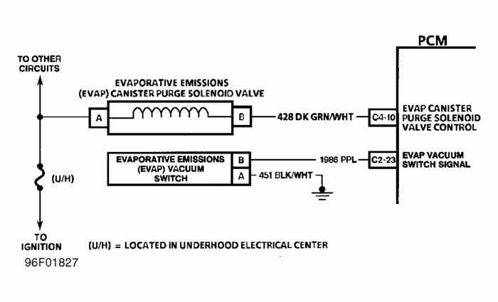
The EVAP vacuum switch is a normally closed switch, mounted in vacuum line between EVAP canister and EVAP solenoid. Battery voltage is supplied to switch through a pull-up resistor in the PCM. When PCM commands EVAP canister purge solenoid valve open (purge on), engine vacuum draws the evaporative emissions from the canister and EVAP switch opens (signal voltage high) providing feedback to PCM, indicating EVAP system is operating. When PCM commands purge off, the EVAP vacuum switch closes (signal voltage low), confirming that purging has ceased.
Diagnostic Procedures Perform On-Board Diagnostic (OBD) System Check. After performing OBD system check, go to next step.
If DTC P0443 is present, diagnose this DTC first. Turn ignition on, with engine off. Using scan tool, check EVAP vacuum switch status. If scan tool indicates that EVAP vacuum switch is not purging, go to next step. If scan tool indicates that EVAP vacuum switch is purging, go to step 5).
Start engine. Using scan tool, command EVAP canister purge solenoid on, while observing EVAP vacuum switch status. If scan tool indicates that canister is purging when solenoid is commanded on, see DIAGNOSTIC AIDS. If solenoid is not purging when commanded on, go to next step.
Turn ignition off. Disconnect purge hose from EVAP vacuum switch. Connect a vacuum gauge to canister side of EVAP switch. Start engine. Using scan tool, command EVAP canister purge solenoid on, while observing vacuum gauge. If vacuum gauge indicates vacuum reading close to engine vacuum when solenoid is commanded on, go to next step. If vacuum reading is close to engine vacuum, go to step 7).
Disconnect EVAP vacuum switch harness connector. If scan tool indicates PURGE, go to step 9). If scan tool does not indicate PURGE, go to next step.
Turn ignition off. Disconnect PCM connector C2. Using DVOM, check continuity between EVAP vacuum switch signal circuit and ground. If DVOM reads infinity, go to step 10). If DVOM does not read infinity, go to step 12.
Disconnect vacuum harness from EVAP canister purge solenoid and connect vacuum gauge to manifold side of vacuum harness. If normal manifold vacuum is indicated, go to next step. If manifold vacuum is not indicated, go to step 13).
Rotate vacuum harness connector enough to reconnect only the manifold vacuum supply hose to solenoid. Connect vacuum gauge to the other port on solenoid. Using scan tool, command EVAP canister purge solenoid on, while observing vacuum gauge. If vacuum is indicated when solenoid is commanded on, go to step 14). If vacuum is not indicated when solenoid is commanded on, go to step 15). Replace EVAP vacuum switch. After replacing vacuum switch, go to step 16). Check connections at PCM. After repairs, go to step 16).
Replace PCM. Program replacement PCM using required equipment. After replacing PCM, go to step 16).
Repair signal circuit shorted to ground. After repairs, go to step 16).
Check for blocked or restricted manifold vacuum port. Check for kinked or leaking hose between EVAP solenoid and intake manifold. Repair as necessary. After repairs, go to step 16). If vacuum port and vacuum lines to affected components are okay, go to next step. Check for restricted, kinked or leaking hose between EVAP solenoid and vacuum switch. After repairs, go to step 16).
Replace EVAP solenoid. After replacing solenoid, go to next step.
Using scan tool, select DTC, CLEAR INFO function. Start and warm engine to normal operating temperature. Select DTC, SPECIFIC, then enter DTC P0441. Operate vehicle within conditions for setting this DTC. If scan tool indicates that this test ran and passed, go to next step. If scan tool did not indicate that this test ran and passed, repeat step 2).
Using scan tool, select CAPTURE INFO, REVIEW INFO function. If any undiagnosed DTC(s) are displayed, go to applicable DTC test.
Image (Click to make bigger)
Thursday, November 25th, 2010 AT 10:58 PM


