FWD AXLE SHAFT
Removal
Raise and support vehicle.
Remove front wheels.
Drain transaxle if removing right or both axle shafts.
Draining transaxle is unnecessary if removing left axle shaft only. Spread locking tab on spindle nut and remove nut.
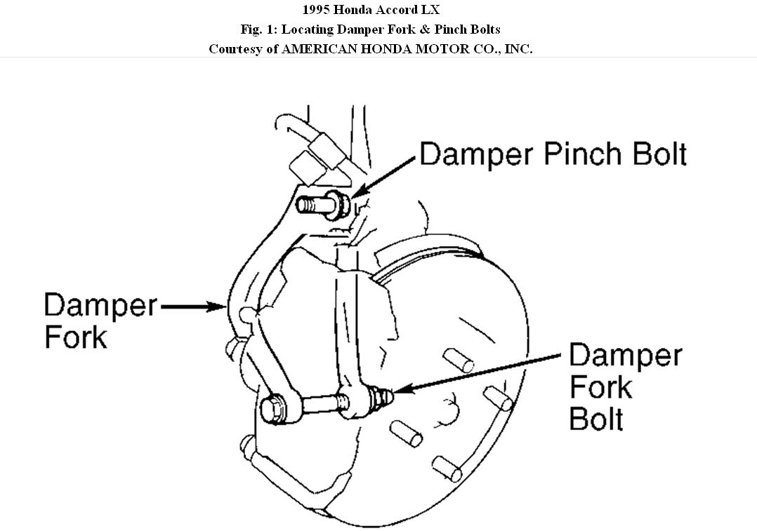
Remove damper fork bolt and damper pinch bolt.
Remove damper fork. See Fig. 1.
Remove lower ball joint cotter pin, and loosen castle nut half length of ball joint threads.
Using a ball joint puller, separate ball joint from front hub.
Remove ball joint castle nut.
Lower control arm and steering knuckle.
Pull steering knuckle outward and remove axle shaft from hub assembly.
If necessary, use a plastic hammer to drive axle shaft out of hub.
NOTE: DO NOT pull on inner CV joint or disassembly may occur. DO
NOT damage seals.
Using a large screwdriver, carefully pry inner CV joint and shaft assembly about.5" (12.7 mm) out of transaxle, dislodging retaining ring from its groove at end of drive axle. Grip both sides of inner CV joint and remove axle shaft and CV joint from vehicle.
NOTE: DO NOT attempt to disassemble outer CV joint; it must be replaced as an assembly. On inner CV joint, mark rollers and roller grooves for reassembly reference.
Disassembly
Remove axle shaft from vehicle, and place it on work bench.
Remove and discard inner CV joint boot clamps.
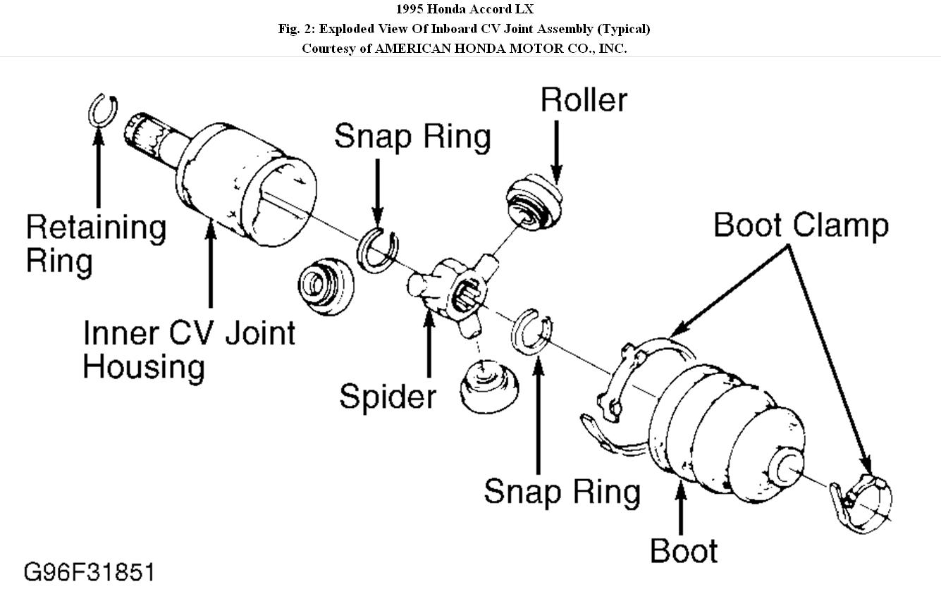
Slide boot toward outer CV joint to access inner CV joint. See Fig. 2.
Index axle shaft, inner CV joint housing and spider roller to ensure reassembly in original positions.
Remove housing from spider assembly.
Index rollers and spider to ensure reassembly to original locations.
Remove rollers from spider.
Remove snap ring securing spider to axle shaft, and remove spider.
Remove snap ring, and slide boot off axle shaft.
Remove outer CV joint boot clamps.
Slide boot off axle shaft inner CV joint end.
DO NOT attempt to disassemble outer CV joint.
Replace outer CV joint as an assembly only.
Reassembly
Thoroughly clean and inspect axle shaft for wear.
Replace all defective parts.
Wrap axle shaft splines using vinyl tape to prevent damage to dynamic damper and CV joint boots.
Install outer CV joint boot, dynamic damper and inner CV joint boot.
Remove vinyl tape from axle shaft.
DO NOT install CV joint boot clamps yet.
Install snap ring in groove on axle shaft.
Install spider on axle shaft by aligning marks made at disassembly.
Install snap ring into groove.
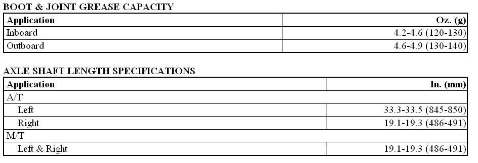
Pack outer CV joint boot with specified amount of molybdenum disulfide grease. See BOOT & JOINT GREASE CAPACITY.
Lube spider and inside bores of rollers.
Ensure rollers are aligned with marks made at disassembly and high side of rollers face outward.
Install rollers.
Pack inner CV joint and boot with molybdenum disulfide grease.
Align housing marks made at disassembly and install housing on spider assembly.
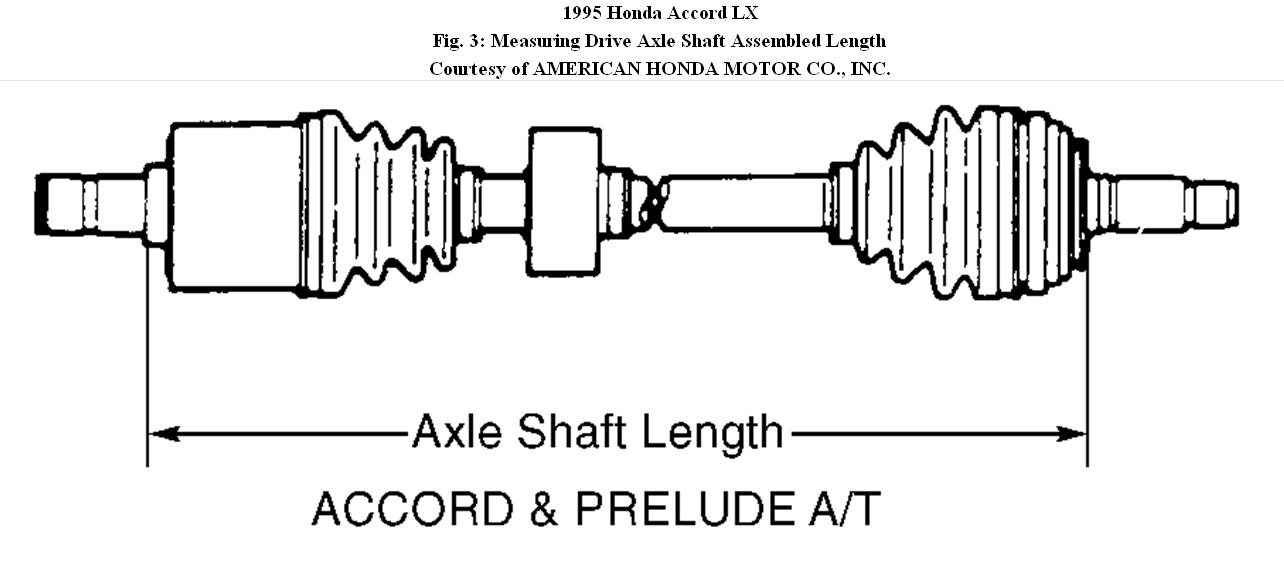
Adjust standard length of axle shaft. See Fig. 3. Refer to AXLE SHAFT LENGTH SPECIFICATIONS.
Position boots halfway between full compression and full extension
and install boot clamps.
CAUTION: Always use a NEW retaining ring when installing axle shaft.
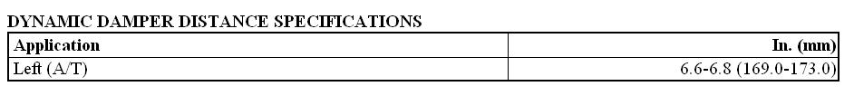
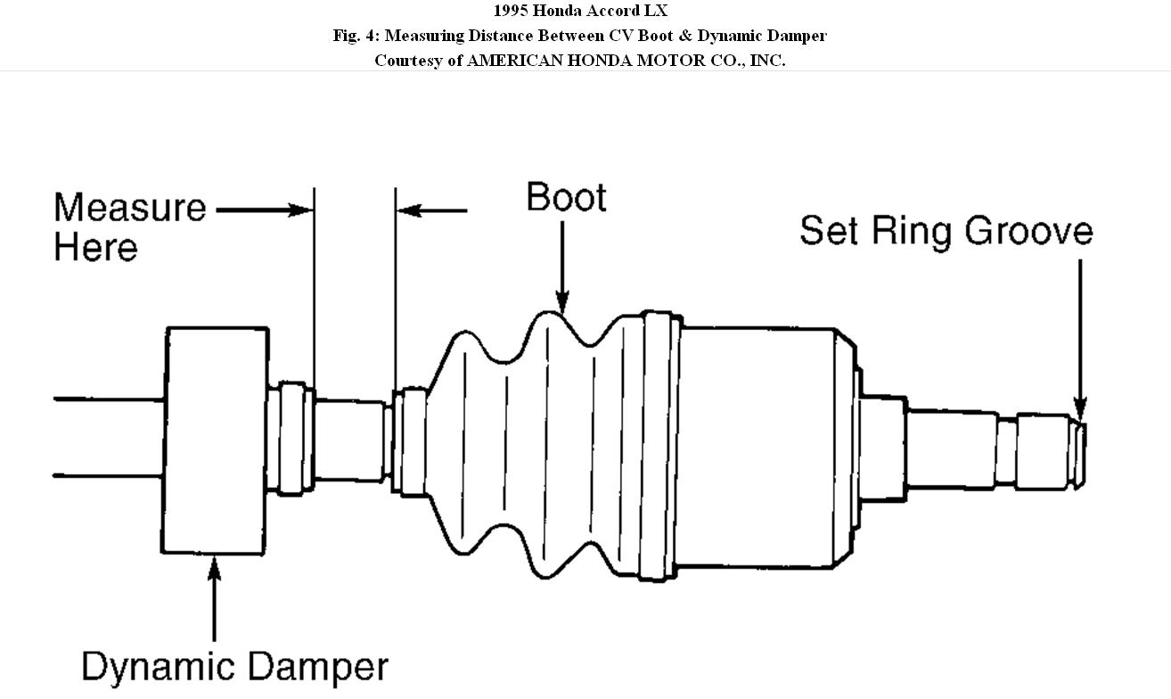
Position dynamic damper to correct distance from edge of boot. See Fig. 4. See DYNAMIC DAMPER DISTANCE SPECIFICATIONS.
Bend down lock tab of each boot clamp and lightly tap doubled-over portion of boot clamp to reduce clamp height.
Install a NEW retaining ring on end of inner CV joint, and install axle shaft.
Installation
Slide axle shaft into transaxle or intermediate shaft.
Ensure inner joint housing locks into differential side gear groove and joint sub-axle bottoms in differential or intermediate shaft.
Install damper fork over axle shaft and onto lower control arm.
Install damper in damper fork so aligning tab aligns with slot in damper fork.
Loosely install damper pinch bolt using NEW damper fork nut.
Pull hub assembly away from axle shaft, and slide axle into hub assembly.
Install and lightly tighten spindle shaft nut.
Position ball joint in hub.
Raise lower control arm using floor jack, and install ball joint nut.
Tighten lower ball joint nut to specification.
Install and secure cotter pin.
Remove floor jack.
Tighten spindle nut to specification.
Install wheels.
Lower vehicle.
With vehicle weight on damper, tighten damper pinch bolt to
specification.
Refill transaxle.
Images (Click to make bigger)
Sunday, January 30th, 2011 AT 2:59 PM