Based on information from our database, the fault code is for ATC mode door stall failure.
TEST 10A - ATC MODE DOOR FEEDBACK OR STALL FAILURE
1. Locate BCM behind right kick panel. Turn ignition off and connect DRB. Turn ignition on and engine off. Using DRB voltmeter, backprobe BCM 5-volt supply circuit Black connector terminal No. 6 (Pink/Dark Blue wire). If voltage is less than 10 volts, go to next step. If voltage is greater than 10 volts, repair Pink/Dark Blue wire for short to battery voltage. Perform VERIFICATION TEST.
2. If voltage is less than 4 volts, go to next step. If voltage is greater than 4 volts and less than 10 volts, go to step 6).
3. Turn ignition off. Disconnect BCM connectors, located above right kick panel. Using DRB ohmmeter, probe BCM Black connector terminal No. 6 (Pink/Dark Blue wire). If resistance is greater than 5 ohms, go to next step. If resistance is less than 5 ohms, repair short to ground on Pink/Dark Blue wire. Perform VERIFICATION TEST.
4. Using external ohmmeter, measure resistance between BCM Bone connector terminal No. 15 (Gray/Tan wire) and BCM Black connector terminal No. 6 (Pink/Dark Blue wire). If resistance is less than 2000 ohms, go to next step. If resistance is greater than 2000 ohms, replace BCM. Perform VERIFICATION TEST.
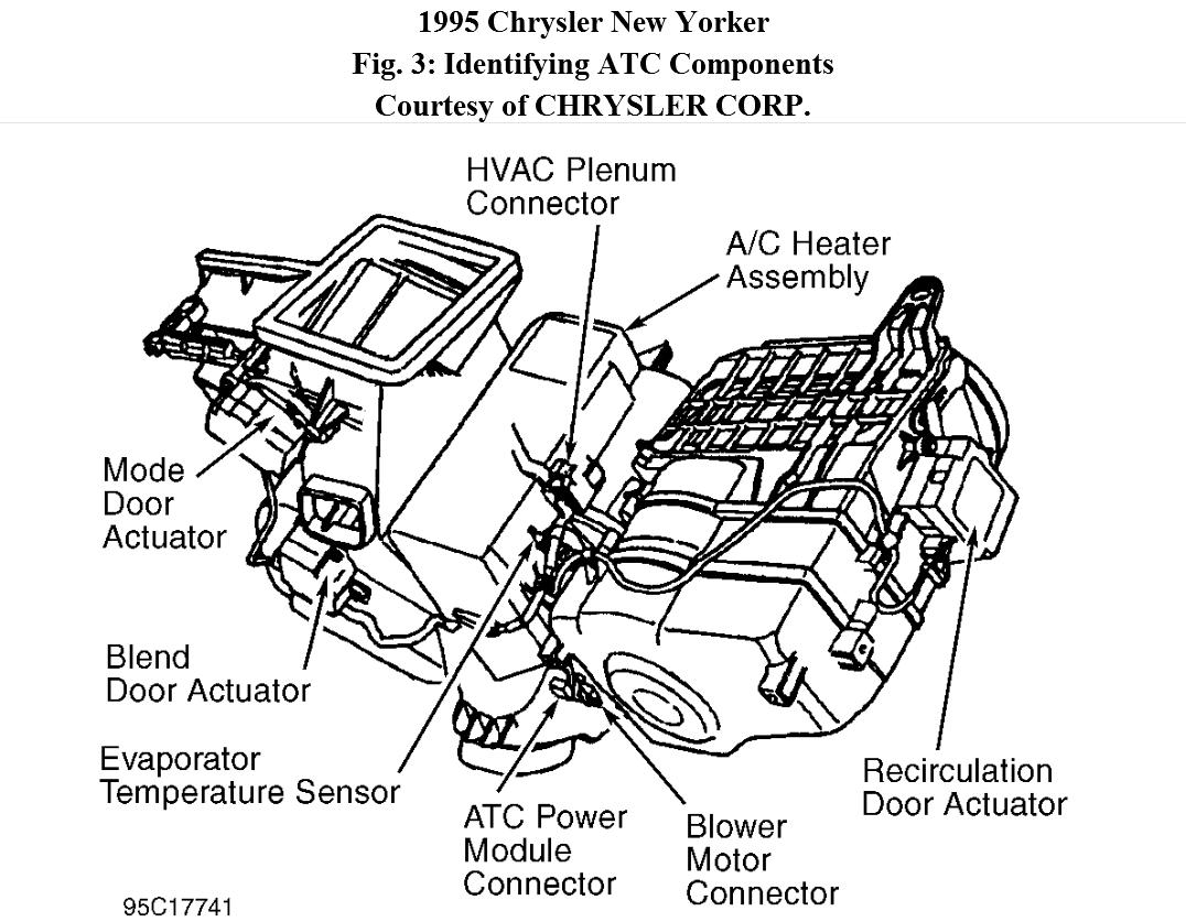
5. Disconnect blend door actuator, located to left of A/C-heater unit. Using external ohmmeter, measure resistance between BCM Bone connector terminal No. 15 (Gray/Tan wire) and BCM Black connector terminal No. 6 (Pink/Dark Blue wire). If resistance is less than 2000 ohms, replace mode door actuator. Perform VERIFICATION TEST. If resistance is greater than 2000 ohms, replace mode door actuator. Perform VERIFICATION TEST. See Fig. 3.
6. Using DRB voltmeter, backprobe HVAC plenum 10-pin connector terminal No. 6 (Pink/Dark Blue wire), located near top center of A/C-heater unit. See Fig. 3. If voltage is greater than 4 volts, go to next step. If voltage is less than 4 volts, repair open Pink/Dark Blue wire between HVAC plenum 10-pin connector and BCM Black connector. Perform VERIFICATION TEST.
7. Using DRB voltmeter, backprobe BCM Gray connector terminal No. 4 (Red wire), located above right kick panel. If voltage is 0.3-10.0 volts, go to step 11). If voltage is less than 0.3 volt, go to next step. If voltage is greater than 10 volts, repair short to battery voltage in Red wire. Perform VERIFICATION TEST.
8. Using DRB voltmeter, backprobe HVAC plenum 10-pin connector terminal No. 7 (Red wire). If voltage is less than 0.3 volt, go to next step. If voltage is 0.3 volt or greater, repair open Red wire between BCM Gray connector and HVAC plenum 10-pin connector. Perform
VERIFICATION TEST.
9. Turn ignition off. Disconnect HVAC plenum 10-pin connector and BCM Gray connector. Inspect connectors and clean or repair as necessary. Using DRB ohmmeter, probe BCM Black connector terminal No. 4 (Red wire). If resistance is less than 5 ohms, repair short to ground in Red wire. If resistance is greater than 5 ohms, go to next step.
10. Check mode air door travel. Remove mode air door actuator, and rotate door shaft in both directions. Ensure door moves smoothly and stops at both ends of its travel. Repair or replace linkage and/or mode air door as necessary. Perform VERIFICATION TEST.
11. Turn ignition off and close all doors. Ensure courtesy lights are off. Wait one minute. Using DRB ohmmeter, backprobe BCM Bone connector terminal No. 15 (Gray/Tan wire). If resistance is less than 60 ohms, go to next step. If resistance is greater than 60 ohms, repair open Gray/Tan wire between BCM Bone connector terminal No. 15 and HVAC plenum 10-pin connector terminal No. 5.
12. Ensure BCM connectors are connected. Turn ignition on and engine off. Using DRB voltmeter, backprobe BCM Black connector terminal No. 22 (Dark Blue/White wire). Turn recirculation switch off. Turn panel switch on. Turn recirculation switch on, and observe voltage change. If voltage becomes greater than 10 volts, go to next step. If voltage remains less than 10 volts, replace BCM. Perform VERIFICATION TEST.
13. Using external voltmeter, backprobe HVAC plenum 10-pin connector terminal No. 2 (Dark Green/Yellow wire). Set panel switch, then defrost switch and then bi-level switch to ON position, and observe voltage change. If voltage increases to more than 10 volts, go to step 15). If voltage remains less than 10 volts, go to next step.
14. Ensure BCM connectors are connected. Turn ignition on and engine off. Using external voltmeter, backprobe BCM Black connector terminal No. 16 (Dark Green/Yellow wire). Set panel switch, then defrost switch and then bi-level switch to ON position, and observe voltage change. If voltage increases to more than 10 volts, repair open Dark Green/Yellow wire between BCM Black connector and HVAC plenum connector. Perform VERIFICATION TEST. If voltage remains less than 10 volts, replace BCM. Perform VERIFICATION TEST.
15. Turn ignition off. Disconnect BCM Black connector. Disconnect HVAC plenum 10-pin connector. Check connectors and clean and/or repair as necessary. Using external ohmmeter, measure resistance in Dark Blue/White wire between BCM Black connector terminal No. 22 and HVAC plenum 10-pin connector terminal No. 1. If resistance is less than 5 ohms, go to next step. If resistance is greater than 5 ohms, repair open Dark Blue/White wire between BCM Black connector and HVAC plenum connector. Perform VERIFICATION TEST.
16. Check mode air door travel. Remove mode air door actuator, and rotate door shaft in both directions. Ensure door moves smoothly and stops at both ends of its travel. Repair or replace linkage and/or blend air door as necessary. Perform VERIFICATION TEST.
Image (Click to make bigger)
Sunday, June 3rd, 2012 AT 10:07 AM