Normal Mode
1. Before retrieving trouble code(s), verify MIL on instrument panel comes on with ignition on and engine off. The MIL should go off when engine is started.
2. If MIL does not come on with ignition on and engine off, see appropriate DIAGNOSTIC CIRCUIT CHECK chart under TROUBLE CODE CHARTS.
3. If MIL remains on, self diagnostic system has detected a malfunction or abnormality. Ensure battery voltage is greater than 11 volts and charging system is okay. Warm engine to normal operating temperature.
4. Apply parking brake. Shift the transmission/transaxle into Neutral (M/T) or Park (A/T). Turn A/C and all accessories off. Ensure throttle is in idle position.
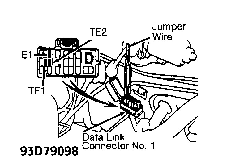
5. Turn ignition on with engine off. Install Jumper Wire (SST 09843 18020) between terminals TE1 and E1 in appropriate Data Link Connector (DLC). See Fig. 1.
NOTE: DLC No. 1 is used on all models except Camry 2.2L and Supra. On Camry 2.2L and Supra DLC No. 2 is used. See Fig. 1.
6. Count number of flashes from MIL on instrument panel. If system is operating properly (with no trouble codes), MIL will flash continuously and evenly. See Fig. 2.
7. If MIL will not flash, check TE1 and E1 wiring circuit. See appropriate DIAGNOSTIC CIRCUIT CHECK chart under TROUBLE CODE CHARTS. See ECM LOCATION.
8. If trouble code exists, digits of trouble code will be flashed at approximately 1/2 second intervals. A 1 1/2 second pause separates first and second digits of code. See Fig. 2.
9. If more than one trouble code is stored, a 2 1/2 second pause will occur before next trouble code is flashed. Once all trouble codes are displayed, a 4 1/2 second pause will occur then trouble code(s) will be
repeated.
10. Trouble codes are displayed in order of smallest to largest. After trouble codes are retrieved, remove jumper wire to exit Normal Mode. See NOTES ON TROUBLE CODES. For additional information on
trouble codes, see TROUBLE CODE DIAGNOSTIC HINTS table under SELF DIAGNOSTIC SYSTEM and appropriate TROUBLE CODE IDENTIFICATION table under TROUBLE CODE
IDENTIFICATION.
NOTE: To repair failure causing trouble code, refer to proper trouble code chart under TROUBLE CODE CHARTS. Once repairs for trouble code are made, trouble
code must be cleared from ECM memory. See CLEARING TROUBLE CODES.
TROUBLE CODE IDENTIFICATION
Code System Affected (1) Normal Mode (1) Test Mode Probable Cause
12 RPM Signal ON N/A Distributor, Starter Or Circuit, ECM
13 RPM Signal ON ON Distributor Or Circuit, ECM
14 Ignition Signal ON N/A Ignitor Or Circuit To ECM, ECM
21 (2) No 1 Oxygen Sensor Signal ON ON No. 1 Oxygen Sensor/ Heater Or Circuit,
ECM
22 Engine Coolant Temperature Signal ON ON Engine Coolant Temp Sensor Or Circuit,
ECM
24 Intake Air Temperature Sensor Signal ON ON Intake Air Temp Sensor Or Circuit, ECM
25 Lean Air/Fuel Mixture ON ON Loose Ground, Injector Or Circuit,
Oxygen Sensor/Heater Or Circuit, Fuel
Pressure, Ignition, Airflow Meter PAIR
System. ECM
26 Rich Air/Fuel Mixture ON ON Loose Ground, Injector Or Circuit, Fuel
Pressure, Engine Coolant Temp Sensor,
Airflow Meter Compression, ECM
28 (3) No 2 Oxygen Sensor Signal ON ON No 2 Oxygen Sensor/ Heater Or Circuit,
ECM
31 Airflow Meter Signal Circuit ON ON Airflow Meter Or Circuit, ECM
32 Airflow Meter Signal Circuit ON ON Airflow Meter Or Circuit, ECM
35 BARO Sensor ON ON ECM
41 TP Sensor Signal ON ON Throttle Position Sensor Or Circuit, ECM
42 Vehicle Speed Sensor Signal OFF OFF Vehicle Speed Sensor Or Circuit, ECM
43 Starter Signal N/A OFF Starter Signal Circuit, Ignition Switch Or
Circuit, ECM
51 Switch Condition Signal N/A OFF A/C Switch Circuit, Park/Neutral Switch
Or Circuit, TPS Or Circuit, ECM
52 (4) Front Knock Sensor Signal ON N/A Front Knock Sensor Or Circuit, ECM
53 Knock Control Signal ON N/A ECM
55 (5) Rear Knock Sensor Signal ON N/A Rear Knock Sensor Or Circuit, ECM
71 EGR System Malfunction ON ON EGR System, EGR Temp Sensor Or
Circuit, EGR VSV, ECM
81 Transmission Control Module ON N/A ECT1 Circuit
Communication
83 Transmission Control Module ON N/A ESA1 Circuit
Communication
N/A ESA2 Circuit
Mar 1, 2012 at 12:37 AM