1992 Lexus SC 400 A/C

Tiny
MONT.AUTO
  • MEMBER
  • 1992 LEXUS SC 400
  • 4.0L
  • V8
  • RWD
  • AUTOMATIC
  • 120,000 MILES
Although the main heater and defroster relays appear to be working well and have power (both the main power and the ignition related circuit) the A/C dash mounted control unit is dead and the interior HVAC cooling fan is not operational. The main dash mounted A/C & Radio switch appears to control the ground circuit. The Radio switch works. The Red/Grey lead to the dash mounted A/C Control unit is supplying constant 12 volt power. The Blue/Red lead supplies 12 volt ignition related power. The Black with Red stripe lead supplies 12 volt ignition based power to the Cooling Fan Computer Control unit. We acquired another A/C dash mounted Control unit (not yet received) but, it seems unreasonable that the whole unit would all fail at once. What are we missing?
Saturday, November 14th, 2015 AT 1:31 AM

18 Replies

Tiny
HMAC300
  • MECHANIC
  • 48,601 POSTS
Not real sure on this but the 60 amp fusible link in lh side junction block which powers heater relay may be it. It turns into a blue wire then white green then blu/yellow in pics. Also powers blower motor and resistor. You didn't mention that so I am assuming that may be the problem.
Was this
answer
helpful?
Yes
No
Saturday, November 14th, 2015 AT 7:28 AM
Tiny
MONT.AUTO
  • MEMBER
  • 32 POSTS
Yes, the 60A fusible link is providing constant power to the heater relay and the ignition circuit is providing power to the #1 terminal. The replacement A/C Control arrived. Let's keep in touch and I will advise the results of the A/C Control swap. We are also replacing the A/C / Radio switch and the Cooling Fan Control unit. Any other ideas?
Was this
answer
helpful?
Yes
No
Saturday, November 14th, 2015 AT 2:16 PM
Tiny
HMAC300
  • MECHANIC
  • 48,601 POSTS
Other ideas because after I read what you had checked you didn't say anything about that so I kind of figured that was the problem. I just checked wiring for radio which there are two fuses one fuse is inside car and powers radio, antenna etc. The ground is at rh center of dash. Just for the hell of it you might try jumping the two items in pic and see if it makes a difference. One is temp sensor and those can do all kinds of screwy things. They both go to the cooling fan ecu and may be the problem, might be the wrong direction but worth a try and doesn't take very long.
Was this
answer
helpful?
Yes
No
Saturday, November 14th, 2015 AT 3:51 PM
Tiny
MONT.AUTO
  • MEMBER
  • 32 POSTS
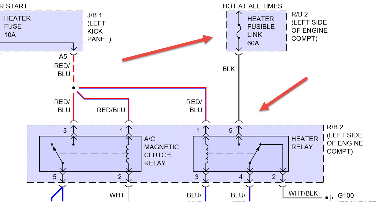
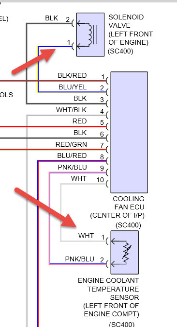
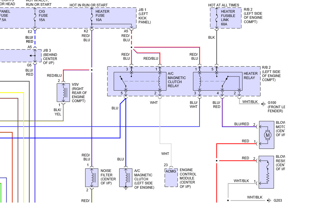
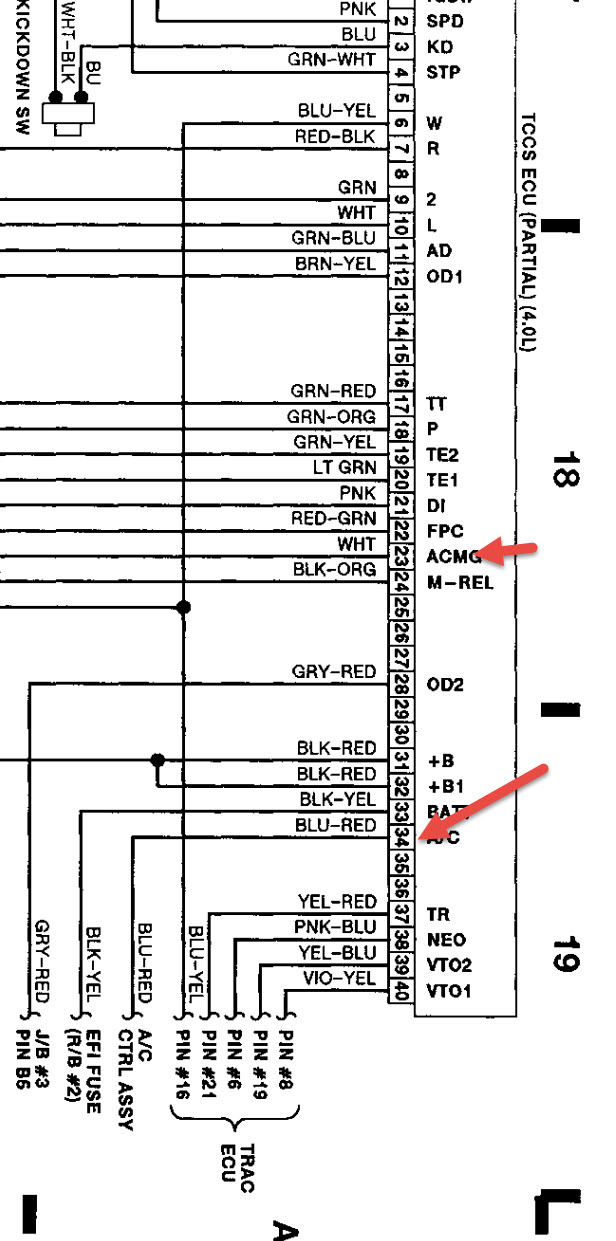
Just a brief follow-up to our earlier correspondence. We jumped #2 to #10 on the cooling fan control but, no change. In looking at the electrical schematics we did notice that the A/C Pressure Switch wasn't grounded but, grounding that line (#5 in connector A14) made no difference. Looking at the 3 connectors to the rear of the A/C control (A12, A13 & A14) the charts imply 2 power leads to connector A12 (#1 & #15), one ground to connector A12 (#7) and one ground lead to connector A14 (#5). These are all engaged per spec. But, the control unit is still dead. This result is consistent even though we replaced the cooling fan control, A/C control unit and Temp./Radio switch with others that came from vehicles where the system was working. We are able to control the heating/cooling fan by jumping the Heater Relay (using a rheostat to adjust RPM). Same for rear window defroster with a toggle switch. It should be possible to control the servo motors with a toggle switch and the A/C output with some form of thermostat. I mention circumventing the Automatic Climate Control because we have installed an older reworked Chevy 5.7L V8 with a six speed double over drive manual into this 1992 Lexus SC400 (we call it a "Chevus"); meaning, we are applying 1960's technology to a 1990's style vehicle (no computer, no FI - just a Holley 750, etc.). Accordingly, some things have changed. Everything works regardless of which drive train is installed but, for some unknown reason the A/C control is dead. I should add that although the original A/C compressor and system have remained intact, the compressor is not yet electrically attached but, it doesn't seem that the lack of this component should cause the remainder of the HVAC system to fail. Or, are we missing something? We noticed that the A/C compressor's connection has three leads whereas the clutch probably only needs two leads (a + and a -) to be engaged. Can you explain the third lead? Also, if we convert the system to manual HVAC controls (we have already installed a manual heater control valve for the heater core) can you recommend a Toyota vehicle(s) from which we could obtain a suitable (manual) temperature control for this A/C unit? Have a good day.
Was this
answer
helpful?
Yes
No
Monday, November 16th, 2015 AT 2:57 PM
Tiny
HMAC300
  • MECHANIC
  • 48,601 POSTS
You guys certainly ask for trouble the pic shows what I have already sent in previous replies. There are two hot leads to compressor one goes to ac control other to clutch. The do show a ground but not a wire. It is a blue wire that turns into grnwhite and goes to ac control. I would have no idea what control to use on this. The pcm tells the relay to engage all of this stuff so maybe because it's being not used right that that is the problem the white wire that goes to relay to tell compressor and control unit that it needs to be turned on. That may be your problem right there.
Was this
answer
helpful?
Yes
No
Tuesday, November 17th, 2015 AT 5:48 AM
Tiny
HMAC300
  • MECHANIC
  • 48,601 POSTS
Give me a couple of hours to dig into this because you aren't using the pcm you may be able to jump connectors at pcm to get your ac to work right without doing the manual thing you are trying to do.
Was this
answer
helpful?
Yes
No
Tuesday, November 17th, 2015 AT 10:48 AM
Tiny
HMAC300
  • MECHANIC
  • 48,601 POSTS
Ia have got lucky and not needed the couple of hours. Try jumping the two wires on ecm pointed out in arrows. See if that makes it work. If it does you are golden
Was this
answer
helpful?
Yes
No
Tuesday, November 17th, 2015 AT 10:53 AM
Tiny
HMAC300
  • MECHANIC
  • 48,601 POSTS
Forgot pic, damn.
Was this
answer
helpful?
Yes
No
Tuesday, November 17th, 2015 AT 10:54 AM
Tiny
MONT.AUTO
  • MEMBER
  • 32 POSTS
Thanks for your continued interest. At first blush, I'm not sure that we are on the same electrical schematic page. I'm referring to the 1992 Lexus Electrical Wiring Diagram Section "K" page 23 entitled "Automatic Air Conditioner" which doesn't present your junction block. I can send a picture of what I'm viewing if you can specify the proper procedure. On the schematic I'm viewing, I can identify a two blue/red wires connected to the A/C dash mounted control unit; one (identified as ACC) feeding pin #15 for connector A12 provides power from the ignition switch to the A/C control and the other (identified as MGC) attached to pin #4 for connector A13 and leads to Engine and ECT ECU. Of course, since the engine is no longer computer controlled, that box has been removed. The only white wire that is visible is connected to pin #8 of connector A12 (identified as MF ACE) and connects to the Air Vent Servo Motor. Are we on the same page? Thanks for your help. Have a good day.
Was this
answer
helpful?
Yes
No
Tuesday, November 17th, 2015 AT 11:34 AM
Tiny
HMAC300
  • MECHANIC
  • 48,601 POSTS
We only have Mitchell not factory ones but if you can find the wire from ac control at pcm connection and jump to the white wire for heater relay everything should work. The schematic I sent is at the pcm not control head and the pcm is what turns on the heater relay/compressor I think to complete the circuit.
Was this
answer
helpful?
Yes
No
Tuesday, November 17th, 2015 AT 12:21 PM
Tiny
MONT.AUTO
  • MEMBER
  • 32 POSTS
Thanks for your continued interest. I apologize for any inconvenience. Attached, please find the Section "K" which I mentioned earlier, much of which probably doesn't apply since we are focused on the A/C dash mounted control unit for which the electrical schematic is displayed on pages 36 & 37 of this file and which documents the connections and wire covering colors for each (Blue/Red being L-R) pin. My assumption is that we are trying to fool the system into believing nothing has changed and that it should function as normal. I've included the entire Section "K" thinking there might be some short cut which isn't obvious when just focusing on the A/C control pages. By the way, you mentioned the "PCM" but, I wasn't able to immediately find any PCM reference that remained in the vehicle. Can you help me out? Lastly, you've already spent more time on this issue than I thought you would (thanks for the courtesy). How do I respectfully add more $ to the kitty? Have a good day.
Was this
answer
helpful?
Yes
No
Tuesday, November 17th, 2015 AT 3:47 PM
Tiny
HMAC300
  • MECHANIC
  • 48,601 POSTS
From what you said now the pcm and all its wiring is gone. In my very first reply I pointed to the ac wire that says ac in to control that is the same wire that needs to connect to heater relay to jump the original pcm wire. Your pic didn't show. The relay that is not working is the ac magnetic clutch relay that powers the clutch and goes full circle back to the control head. On the pcm it was the blue red wire which changes color a couple of times but goes to a blue yellow on control see first reply pic.I think if you put that wire to white wire going to the magnetic clutch relay it will go full circle and work, not sure on that. But that seems to be the way it works. Maybe not.
Was this
answer
helpful?
Yes
No
Tuesday, November 17th, 2015 AT 4:10 PM
Tiny
MONT.AUTO
  • MEMBER
  • 32 POSTS
Thanks for your continued support. As you suggested I shorted the #1 Red/Blue lead and the #2 White lead at the A/C Magnetic Clutch Relay but, no change; meaning, the A/C dash mounted control is still dead. Since the schematic stated that the #2 White colored lead was to go, "To the Engine and ECT ECU<2-7>, I grounded the #1 to #2 short but, still no change. I've scanned the total of our previous correspondence Have a good day.
Was this
answer
helpful?
Yes
No
Tuesday, November 17th, 2015 AT 6:56 PM
Tiny
HMAC300
  • MECHANIC
  • 48,601 POSTS
It won't reach me unless he sends it to me. Ok if you hook up the single arrow on mg clutch relay to single arrow on heater then supply power to the white wire it should work. The white wire gets power from the pcm which I don't know what the hell turns it on though. Mike will send me the schedule i'm sure but won't be til later in day as i'm Mich and him in Cali
Was this
answer
helpful?
Yes
No
Wednesday, November 18th, 2015 AT 6:45 AM
Tiny
MONT.AUTO
  • MEMBER
  • 32 POSTS
Thanks for your support. As you suggested, I maintained the short between the #1 R/B and #2 W lead at the Magnetic Clutch relay (noted above) plus applied 12 volt positive power to the White wire that was originally (when the original Lexus 400L drivetrain was installed) directed "To the Engine and ECT ECU<2-7>" but, still nothing. The solution is probably something simple but, it isn't obvious. Have a good day.
Was this
answer
helpful?
Yes
No
Wednesday, November 18th, 2015 AT 3:03 PM
Tiny
HMAC300
  • MECHANIC
  • 48,601 POSTS
You aren't doing what I said. You keep screwing around with the heater relay and not the magnetic clutch relay. Hooke the heater wire to the BLUE wire#5 on mag clutch relay. Leave the white wire connected to positive leave the other wires as they are the wire I have marked in latest pic goes along with magnetic clutch but the wire leads to the heater control. That shold also bo to #5 on mag relay. Then it should work I think if not then the control head may not be getting power. The ac control switch goes to jb#3 h10 in two places one to control and other tocontrol assembly I have not received the k yet i'll email mike to send it to me.
Was this
answer
helpful?
Yes
No
+1
Wednesday, November 18th, 2015 AT 3:25 PM
Tiny
MONT.AUTO
  • MEMBER
  • 32 POSTS
Sorry for any inconvenience. Sometimes the pin numbers are different on your schematic and mine. So, I will speak in terms of the wire colors. On my schematic, the Magnetic Clutch Relay is fed by the Red/Blue wire off of the 10A Heater circuit. For this relay the Red/Blue wire feeds both the relay coil and the internal switch which ultimately feeds the Magnetic Clutch coil (with a Blue wire) and the A/CIN pin on the dash mounted A/C control unit with a White/Green wire. Adjacent to the Magnetic Clutch relay is the Heater relay wherein the Red/Blue wire only feeds the relay's coil which engages the internal relay switch that connects the 60A Heater circuit to both the blower and a White/Black wire that attaches to a (EB) ground (front side of left fender). To see if energizing the White/Green wire that ultimately attaches to the A/CIN pin on the A/C control unit (D connector #2 pin), I shorted the positions #3 & #5 on the Magnetic Clutch relay but, nothing happened. When I checked further, the Red/Blue wire wasn't providing any power. I then attached a lead directly from the positive side of the battery but, still nothing. I couldn't immediately find the 10A Heater circuit fuse. I thought it might be in the left kick panel but, the manual does not show any 10A HTG in the picture but, shows a 10A HTR within the Schematic. There are two 10A in the picture one labeled MIR-MTB & the other MTB. Significant? I will check them out although since I provided direct power to the White/Green wire with no change, it doesn't seem that's the answer although it may be part of the answer. If it is possible to determine all of the leads which bring power (plus all grounds) to the A/C controller when it is operational, I could adjust the wiring accordingly and see if that resolves the issue. Somehow we are either not feeding the unit with the power it needs or we are missing a ground. As noted earlier, when I originally tested the 3 A/C control connectors, I only found 2 power sources (connector A12 pin #1 (+B) & 15 (ACC)) and 2 grounds (Connector A12 pin 7 (GND) and connector A14 pin 5 (LP). Any thoughts? Thanks for your help.
Was this
answer
helpful?
Yes
No
Thursday, November 19th, 2015 AT 12:47 AM
Tiny
HMAC300
  • MECHANIC
  • 48,601 POSTS
Something is definitely missing between us during explanations of things. Best thing to do check your schematic and make sure all power parts are going to a/c control then hook up blue wire and yellow green or one that goes to ac control for compressor activate the white wire with power on mag clutch relay and see if you have power if not check your junction block 3 as that is where power for control head is supposed to be. Next time you do this my advice would be to leave all connectors hooked up then start screwing around with it. I still don't know what tells the pcm to turn the power on to the mag clutch relay. Sorry I can't do more.
Was this
answer
helpful?
Yes
No
Thursday, November 19th, 2015 AT 6:04 AM

Please login or register to post a reply.

Related Air Conditioner Switch Content

How to Use a Test Light
VIDEO

Sponsored links