Will not stay running

Tiny
RUNNER45
  • MEMBER
  • 1984 JEEP CJ7
  • 4.2L
  • 6 CYL
  • 4WD
  • MANUAL
  • 20,000 MILES
I have the vehicle listed above that I acquired from my brother while I was overseas. I ordered a few parts while awaiting to return home along with asking him questions on the issues he was facing with the vehicle. He told me that everything revolves around the mess in the ge tank and was mechanic verified. However that was 15 years ago. First thing is I replaced all the old rubber fuel lines and flushed the metal lines, with new fuel tank, fuel pump and carburetor (Weber 32/36) when I got it, I noticed the wires are in a bit of a mess, so I have every attention to rewire. But I want to get the ole girl running before I take on that task. Right now, I have the nutter bypass completed along with the team rush upgrade. So the problem happens when cranking her up, she sputter and wants to run so bad while the ignition is in start, but once I turn to run it just shuts off. I have replaced the ignition module, the ignition switch. I am at a lose for words at the moment. But I have looked over many forums and issues people are facing. The only difference is that no ones issues stemmed from a Jeep that has sat this long so I wanted to throw mine out there to see if I get any bites. And help would be appreciated and looks forward to getting the ole girl firing again.

Thanks, TK
Sunday, October 18th, 2020 AT 8:55 PM

14 Replies

Tiny
CARADIODOC
  • MECHANIC
  • 33,742 POSTS
You're describing the classic symptom of a failed ballast resistor, but that was only used with the smaller engine, not the 4.2L, at least not according to the diagram. Still, there is a bypass circuit shown that is used with that resistor.

Battery voltage is drawn down by the starter's high current demand. Couple that with the lower voltage to the ignition coil thanks to the ballast resistor, that makes for a very weak spark during cranking. To overcome that low voltage, there's a means of bypassing the ballast resistor during cranking. Chrysler used to do that with an extra tap on the ignition switch. Ford did that with a tap on their starter solenoid. That is indicated by the red arrow in this diagram. That terminal gets battery voltage switched onto it during cranking, and it is applied directly to the ignition coil positive terminal, (blue arrow).

When there's a break in the circuit between the ignition switch and the ignition coil, the ignition system goes dead, but it will still work during cranking because of that bypass circuit. The place to start is by checking for 12 volts at the ignition coil's positive terminal when the ignition switch is in the "run" position. If it is missing or low, we'll have to diagnose that circuit.
Was this
answer
helpful?
Yes
No
Sunday, October 18th, 2020 AT 9:19 PM
Tiny
RUNNER45
  • MEMBER
  • 10 POSTS
Appreciate the response, I am currently cleaning all grounds to double check that area, and then I’ll report back my findings.
Was this
answer
helpful?
Yes
No
Monday, October 19th, 2020 AT 12:56 PM
Tiny
RUNNER45
  • MEMBER
  • 10 POSTS
So from the looks of it, I get 12V at the coil while in the run position.
Was this
answer
helpful?
Yes
No
Monday, October 19th, 2020 AT 1:55 PM
Tiny
CARADIODOC
  • MECHANIC
  • 33,742 POSTS
Dandy. I should have mentioned to take that reading with everything connected and plugged in, and a test light is faster than a digital voltmeter and in some instances can be more accurate.

You found the engine tries to run while the ignition switch is in the "crank" position, but not in "run". For the next test, go to the starter solenoid and unplug the red / white wire. Now see if the engine still tries to run when cranking it.
Was this
answer
helpful?
Yes
No
Monday, October 19th, 2020 AT 4:35 PM
Tiny
RUNNER45
  • MEMBER
  • 10 POSTS
So what does the red and white wire run to? I currently do not have one of those wires hooked up. And I did it both ways just to confirm.
Was this
answer
helpful?
Yes
No
Monday, October 19th, 2020 AT 5:24 PM
Tiny
CARADIODOC
  • MECHANIC
  • 33,742 POSTS
Ford used three different versions of that starter solenoid, and they all look the same but can not be interchanged. On yours, that red / white wire is tied right to the ignition coil's positive terminal, the same as the wire coming from the ignition switch. If you unplug the red / white wire at the solenoid, you'll find the test light should be bright on the wire when the ignition switch is in "run". You will also find there is no voltage on the terminal on the solenoid where you pulled that wire from. What you will find is 12 volts on that stud when you're cranking the engine. That is the direct battery voltage that is applied to the ignition coil to get a stronger, (normal) spark when battery voltage gets drawn down by the starter.
Was this
answer
helpful?
Yes
No
Monday, October 19th, 2020 AT 5:45 PM
Tiny
RUNNER45
  • MEMBER
  • 10 POSTS
Got it, I’ll go and try this and respond. Thanks
Was this
answer
helpful?
Yes
No
Monday, October 19th, 2020 AT 5:59 PM
Tiny
RUNNER45
  • MEMBER
  • 10 POSTS
When I unplug the wire from the coil it does not try and start.
Was this
answer
helpful?
Yes
No
Monday, October 19th, 2020 AT 6:27 PM
Tiny
RUNNER45
  • MEMBER
  • 10 POSTS
Here is the picture of it. Just in case I’m wrong with this rat nest they called wiring.
Was this
answer
helpful?
Yes
No
Monday, October 19th, 2020 AT 6:28 PM
Tiny
CARADIODOC
  • MECHANIC
  • 33,742 POSTS
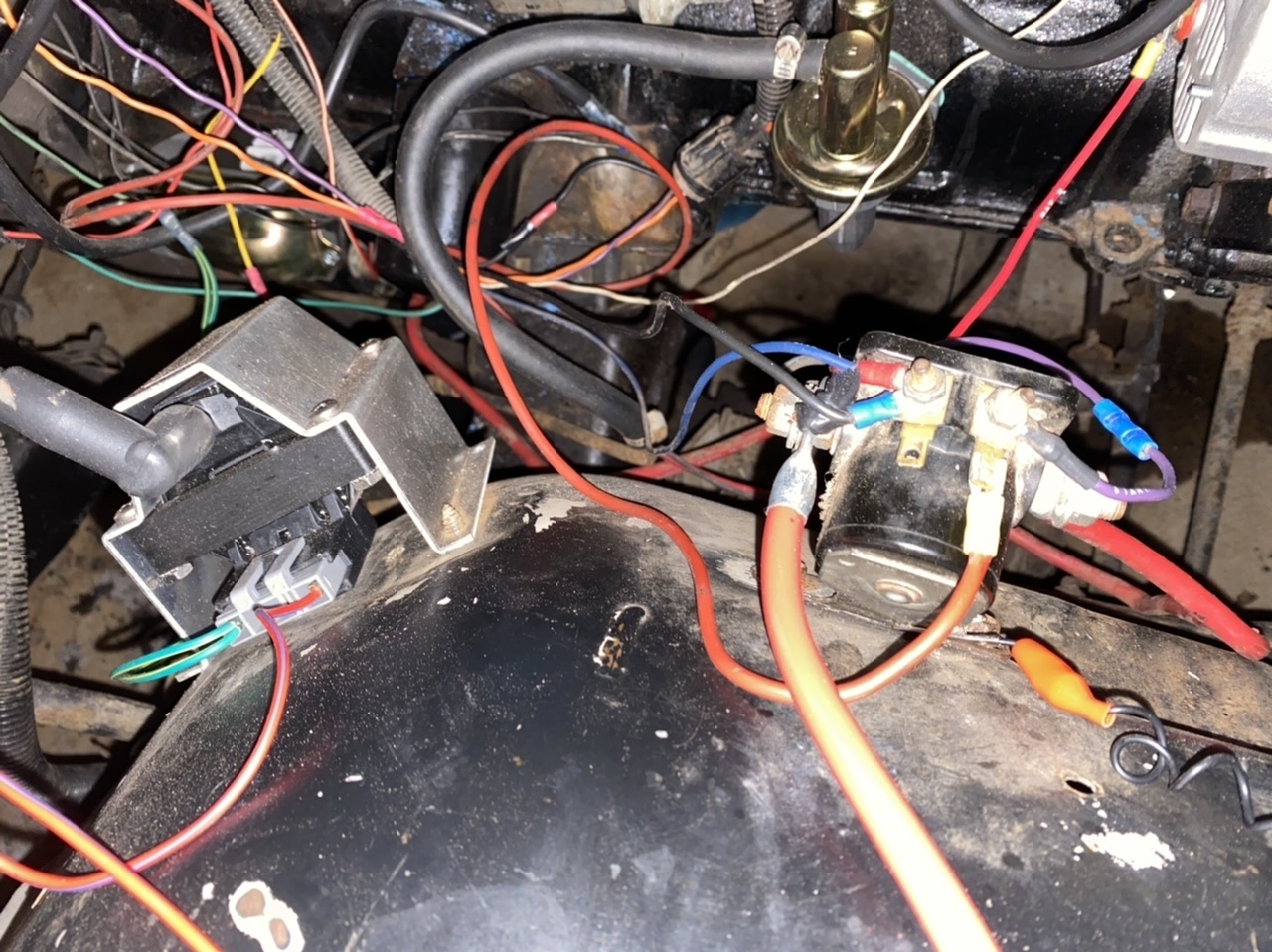
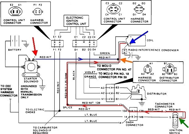
To avoid confusion, we have to use different terminology. If you unplugged the wire at the red arrow, the starter should still crank the engine normally, but if it doesn't try to run, that would be further proof 12 volts isn't getting to the ignition coil through the ignition switch. It is only getting there through the red / white wire, but that only puts it there during cranking.

If, by "does not try to start", you mean the starter doesn't crank the engine, that would occur if the other wire was disconnected, (purple arrow).

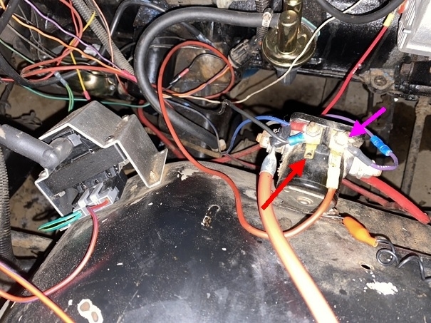
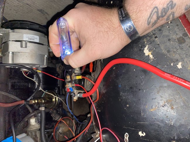
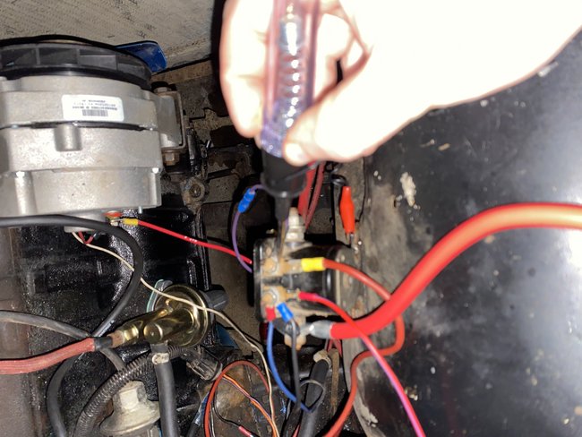
There's too many wires connected to those two smaller studs. Not sure what the story is there.

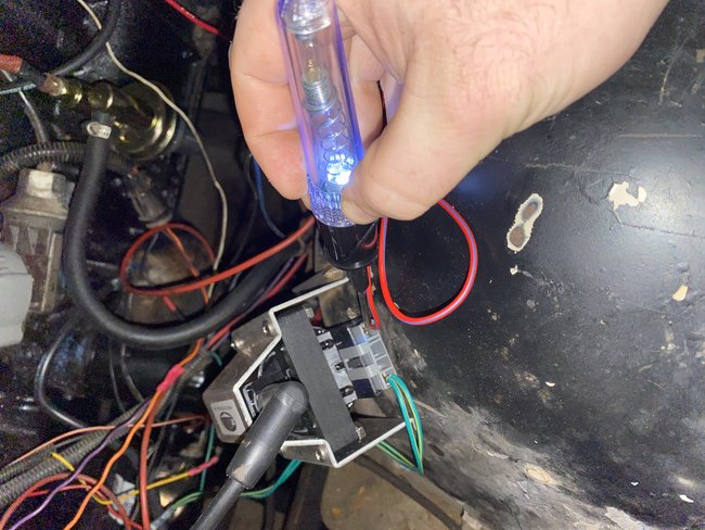
The reason I mentioned using a test light earlier is it will be more accurate for this type of problem. The digital voltmeter is best when we need to know the voltage at a point with high accuracy. Here we only need to know if we have something, nothing, or the voltage is too low. If you unplug the wire at the positive terminal of the ignition coil, then use the voltmeter to see if 12 volts is there with the ignition switch in "run", that's what you'll find as long as just one tiny strand of wire is still intact at a corroded connection or splice, but you'd never get enough current through there to run the ignition system.

Think of the compressed air line in your shop. It has a hundred-foot run, and half way along it, the pipe is 99 percent blocked. If you put a pressure gauge at the end, you'd still find full system pressure as long as no air was flowing. As soon as you tried to run an air tool, pressure would drop to almost nothing. The results of the restriction only show up when you try to get some air volume, or flow. Voltage is electrical pressure, and as long as no current is trying to flow, there can be a corroded splice, a break with carbon tracking in between, or most of the strands of wire are broken, and you'll still see 12 volts with the voltmeter. Test lights, (old fashion test lights with little incandescent bulbs), require current flow to operate. Can't get that current flow when there's a break in the circuit, so the test light will be off, giving the more accurate reading. The same thing can happen when you unplug the "load", in this case the ignition coil. That break in the circuit equates to the blockage in the air line.

Much of the time using the voltmeter doesn't cause this confusion when everything is still connected. In this case though, we don't know if there's current flow through the ignition coil when the ignition switch is in "run" and you're not cranking the engine. To say that a different way, with breaker point ignition systems, when the engine is not being cranked, you have a 50 percent chance it's at rest with the points open, and a 50 percent chance they're closed. If they're closed, current will be flowing through that circuit and the voltage at the coil will be low if there's a break in the circuit. If the points are open, a voltmeter will show full 12 volts even if there's any very high-resistance connection in the circuit. The test light would try to make current flow, then the high resistance would cause it to be off or very dim. That would correctly tell us there's a defect that must be diagnosed.

Instead of breaker points, your switching is done by an electronic module. On some car models, those are designed to turn on the current flow through the ignition coil, then wait for the timing pulse to come from the pick-up coil in the distributor. When that pulse shows up, the module breaks the circuit, the magnetic field inside the ignition coil has to collapse, and it does that very quickly, which is what induces the high voltage in the secondary to make the spark. With this design, current is flowing through the ignition coil and the switching transistor inside the module any time the ignition switch is on and the engine is not rotating. That current can cause the transistor to heat up and reduce its reliability, and it will run the battery down faster. Instead, most manufacturers design the circuit to have no current flow until the pulses start showing up from the pick-up coil, then normal switching takes place.

The reason for describing that is to point out that even with everything connected and plugged in, the ignition module itself can create the open circuit while you're doing the testing with the voltmeter. If this should happen to cause the problem I described, you can see it for yourself by measuring the voltage with the voltmeter, (we'll say you find 12 volts), then touch the test light there at the same time. Now you'll see the voltage drop on the meter. When this happens, trust the test light, not the voltmeter.
Was this
answer
helpful?
Yes
No
Monday, October 19th, 2020 AT 8:08 PM
Tiny
RUNNER45
  • MEMBER
  • 10 POSTS
So the red W/t wire is the coil wire which is disconnected, it has no power to it at all when the key is in the run position and totally unplugged from the solenoid. The wires that consist on the solenoid is the wires that were originally there when this CJ last ran, so I tried not to mess with it to much yet until I can figure it out a bit better. The wires consist of the red on I side going to the alternator, and the black unsure atm, but the blue is the ignition power. The purple on the right side is the start circuit with the start by itself on the far right terminal, and the red on the top right is running into the ignition module. I have only ran a test light for now, but I have posted some pictures to go along with what you said. I know it’s a mess, but I want to fire the ole girl up before I tear down and rewire cause I know it’s a mess. Here is some pictures to follow up.
Was this
answer
helpful?
Yes
No
Monday, October 19th, 2020 AT 8:32 PM
Tiny
RUNNER45
  • MEMBER
  • 10 POSTS
Picture with test light is all in the run position, the S side is showing accurate with no power at the Run position. I hope I read that completely to your explanation. Sorry for the confusion.
Was this
answer
helpful?
Yes
No
Monday, October 19th, 2020 AT 8:35 PM
Tiny
RUNNER45
  • MEMBER
  • 10 POSTS
After contemplating everything that you said, I was able to get the ole girl to fire and run for a free second. However at the moment my fuel lines are running atm, so I’ll have to hook that up and go from there. Thanks for all the help atm.
Was this
answer
helpful?
Yes
No
Tuesday, October 20th, 2020 AT 4:06 PM
Tiny
CARADIODOC
  • MECHANIC
  • 33,742 POSTS
Okay, I think we're making progress. The red line shows the path current takes from the ignition switch to the ignition coil. The blue line shows the path current takes from the starter solenoid during cranking. This one puts what's left of full battery voltage to the ignition coil. We know that path is okay because the engine runs in "crank" mode. With the ignition switch in "run", as in your nifty photos, the 12 volts is not making it to the red / white wire at the solenoid, (red arrow). Since we know the blue circuit is okay, all that leaves for the red circuit is from the ignition switch to the splice, (orange and green arrows).

Put the ignition switch back in the "run" position, then we have to find the break in the red circuit. You could start at the switch, then work your way down the circuit one step at a time, or you could start at the splice and work your way backward. I prefer the shorter method of starting in the middle to break the circuit in half. If the 12 volts is missing there, I have to look in just the first half of the circuit. If I do have 12 volts, I only have to look at the last half. The clinker though is those test points are hidden, buried, or you don't know exactly where they are, so instead, we might just look for whatever convenient test points we can find.

You'll note just to the left of the ignition switch, they show a "tach connector". It's not clear if current has to flow through whatever is connected there or if there is a jumper-wire connector used if the vehicle came without an optional tachometer. Regardless, we know current has to keep going to the dash connector. The service manual isn't clear as to whether that's the bulkhead connector or some other connector. If they're different, the bulkhead connector is still a good spot to find a test point, (and a good spot to find a corroded connection). Check under the dash, then under the hood to see if you have 12 volts on both sides of that connector. There's no reference to a pin-out diagram for any other connector under the dash.
Was this
answer
helpful?
Yes
No
Tuesday, October 20th, 2020 AT 5:22 PM

Please login or register to post a reply.

Sponsored links