here are a few diagnostic procedures that you can do for your performance problem.
TESTING NOTE: Testing procedures described below will apply to all models using the CIS Lambda system unless otherwise noted. Not all models will use all components. PREPARATION FOR TESTING All CIS systems are very sensitive to air leaks. Check condition of rubber boots, hoses, and gaskets. Other areas of leakage are injectors, cold start valve, and PCV system (filler cap and dipstick).
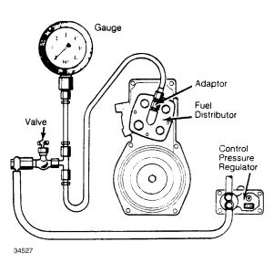
Install a pressure gauge to perform fuel pressure tests. On all models, pressure gauge is installed between the control pressure regulator and the center fitting on fuel distributor. See Fig. 5 .
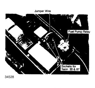
To operate fuel pump with engine not running, disconnect fuel pump relay from relay panel. Insert a jumper wire into sockets that correspond to terminals 30 and 87 on relay. See Fig. 6 .
To operate fuel pump turn ignition on. Place pressure gauge as low as possible in engine compartment, then open and close valve 5 times to bleed gauge. Place valve in open position and hang in convenient location. Turn pump off.
AIR/FUEL MIXTURE CONTROL OR AIR-FLOW SENSOR Remove rubber bellows to expose air-flow sensor plate. Disconnect electrical connectors on auxiliary air valve and control pressure regulator, then operate fuel pump for ten seconds to build up control pressure.
Using extreme care not to damage sensor plate, lift sensor plate slowly with magnet or pliers. Constant resistance due to control plunger pressure should be felt throughout range of lift. Release plate slowly, lever and control piston should follow. See Fig. 7 .
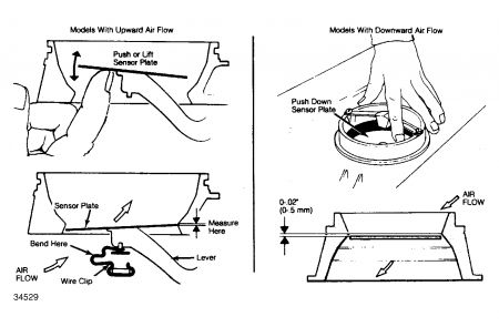
Lift plate, then return it rapidly to lower position. The piston moves more slowly and should be heard hitting the lever. If not, control piston is sticking. Remove 3 screws from fuel distributor and lift off of air flow sensor housing. Be careful not to drop control plunger. See Fig. 8 .
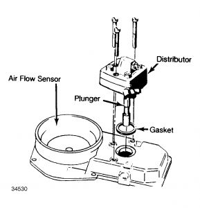
Clean plunger in solvent. Remove any deposits with finger nail; DO NOT use tools. Slide plunger in and out while turning it. If any sticking or binding is felt, replace fuel distributor. Reinstall fuel distributor. Check air flow sensor plate alignment. Plate should be even with bottom rim or 0.02" (0.5 mm) lower. If not, bend spring clip to correct, or reposition stop pin (tap lightly with punch). See Fig. 7 . Plate should be centered in housing. If not, loosen center screw and align plate with 0.004" (.1 mm) feeler gauge at four points around rim. Apply Loctite to screw and install and tighten. COLD ENGINE CONTROL PRESSURE TEST Testing must be done on cold engine. Unplug connectors at auxiliary air valve and control pressure regulator. Place valve on pressure gauge in open position and operate fuel pump. Check pressure quickly. Reading should fall in shaded area of graph. Be sure to check air temperature and read correct area of graph. See Fig. 9 . If control pressure is not correct, retest with new control pressure regulator. No servicing is possible.
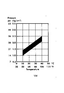
NOTE:Some models have a control pressure regulator with atmospheric pressure compensation. Pressures may vary slightly on these models. Fig. 9: Cold Engine Control Pressure Test Graphs WARM ENGINE CONTROL PRESSURE TEST Connect plug to control pressure regulator. Leave auxiliary air valve and air flow sensor (if equipped) plugs disconnected. Place valve for pressure gauge in open position and operate fuel pump. After about 5 minutes, pressure should rise to indicated level. See Fuel Injection Pressure Testing table. On models with vacuum hose connected to control pressure regulator, leave hose connected to read pressure. Start engine and allow to idle. Pressure should remain the same or rise slightly. On models with control pressure regulator vacuum line, remove and plug hose. Pressure should drop. If pressure does not reach level specified, disconnect plug at control pressure regulator. Check for voltage across terminals with test lamp or voltmeter. At least 11.5 volts should be present. If not, check wiring. If voltage is present and pressure not correct, replace control pressure regulator.
FUEL INJECTION PRESSURE TESTING Application Specifications: psi (kg/cm2 )
Line Pressure68-78 (4.7-5.34
Warm Control Pressure49-55 (3.4-3.9)
Rest Pressure36 (2.4)
Nozzle Opening Pressure51-59 (3.6-4.1)
SYSTEM (LINE) CONTROL PRESSURE TEST
Close valve on pressure gauge. With engine off, operate fuel pump. Pressure should rise to level specified. See Fuel Injection Pressure Testing table.
If pressure is too low, check fuel pump output. Disconnect fuel return line from fuel distributor and run a hose from fuel distributor to container.
Operate fuel pump and measure output after 30 seconds. See Fuel Pump Output Specifications table. If not as specified, check fuel lines, filter, fuel accumulator, and fuel pump.
FUEL PUMP OUTPUT SPECIFICATIONS
Application30 Sec. Flow Rate: Oz. (cc)
Quantum23 (700)
Except Quantum32 (1000)
If pressure is too high, check for kinked or blocked fuel return line. If lines are clear, system pressure regulator must be adjusted. Turn pump off, loosen return line fitting, and relieve pressure.
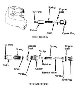
Loosen line pressure regulator nut. Remove shims, spring(s) and plunger. Raise system pressure by adding shims; lower pressure by removing shims. Be sure "O" rings are in good condition. If piston is scored or damaged, fuel distributor must be replaced. See Fig. 10 .
COLD START VALVE, THERMO-TIME SWITCH & HOT START PULSE RELAY
If engine coolant is below 85 °F (30 °C), disconnect plug on cold start valve and connect test lamp across terminals. Remove coil high tension wire to prevent starting. Operate starter.
On models without hot start pulse relay, test lamp will light for several seconds, then go out. On models with relay, lamp will continue to flash off and on.
If lamp does not light, test thermo-time switch for continuity below opening temperature. If good, check wiring to starter terminal.
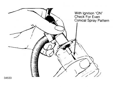
Remove cold start valve from manifold but leave fuel line connected. Place valve in a container. See Fig. 11 . Connect a jumper wire from one terminal to ground, and from other terminal of cold start valve to a switch. The other side of switch should be connected to a source of battery voltage.
CAUTION: Do not connect wire directly to battery. Extreme fire danger is probable due to atomized fuel. Sparks may result if wire is touched to battery.
Operate fuel pump. Turn switch to "ON" position. Cold start injector should spray. Turn switch "OFF", but leave fuel pump running. Injector should not spray. Wipe off nozzle and check for leakage. With pump running, no drops should form within one minute.
Replace cold start valve if faulty. Install original valve if good, making sure that "O" ring is properly positioned.
FUEL INJECTORS
Remove injectors but leave hoses connected. Place injectors in individual measuring containers. With sensor plate in idle position, connect jumper wire in place of fuel pump relay.
Disconnect fuel pump when measuring container with highest level of fuel reaches specified capacity. See VW & Audi Fuel Injector Specificationstable.
Compare amounts of fuel in measuring containers. Fuel should not vary by more than specified amount. Repeat test with sensor plate in full throttle position.
VW FUEL INJECTOR SPECIFICATIONS
Application Fuel Capacity: Oz. (cc)
Idle.58-.78 (17-23)
Full Throttle2.43-2.98 (72-88)
AUXILIARY AIR VALVE
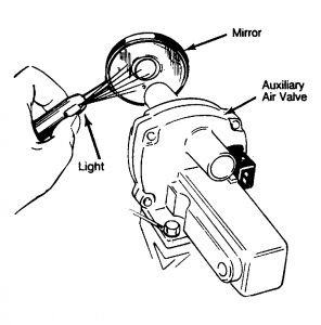
Disconnect hoses from auxiliary air valve. Use a mirror and small flashlight to inspect valve. See Fig. 13 . At room temperature, valve should be slightly open. If equipped, disconnect wires from air flow sensor. With ignition switch "ON" valve should cover opening within 5 minutes.
If valve does not operate properly, check for power at connector with engine running. Connect a test lamp across connector terminals. If lamp does not light, check fuse and wiring.
If lamp lights, check resistance of auxiliary air valve. If no resistance is measured, valve is defective. Ensure electrical connections are tight and terminals are clean, prior to measuring resistance.
LAMBDA CONTROL SYSTEM CHECKS
PREPARATION FOR CHECKS
NOTE: The frequency valve is operated by pulsating voltage from the electronic control unit. By measuring this signal, certain functions of the system can be tested. A special tester (Bosch KDJE 7453) is recommended, but a high-quality dwell meter may be used instead.
Connect dwell meter to testing connector. Connector is located on behind throttle valve housing (Black/White wire).
Set meter on 4-cyl. scale. Connect positive lead of voltmeter to battery and negative lead to pin 3 of diagnostic plug.
Start engine and run until warm. Disconnect oxygen sensor and observe meter needle (should not fluctuate). Place a piece of tape on meter face to indicate 50% position.
OPERATION CHECK
Remove fuel pump relay and connect jumper wire across sockets corresponding to terminals 30 and 87. If equipped, remove plug at air flow sensor. Turn ignition "ON".
Frequency valve should operate, making a buzzing noise. Dwell meter should indicate 45-65 °. Disconnect wire from oxygen sensor and touch wire end to ground. Readings on dwell meter should rise. Ground one end of a 1.5 volt flashlight battery, and touch positive end to sensor wire. Readings should drop to less than 15 °.
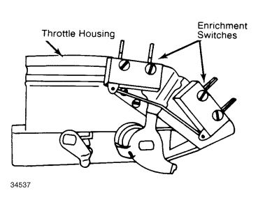
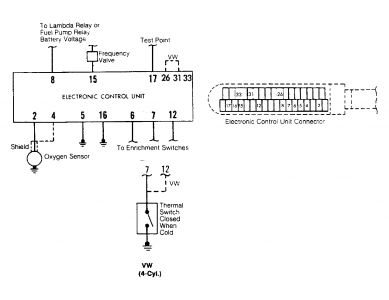
On models with throttle enrichment switch, operate throttle. Readings should be higher at idle or wide open throttle. See Fig. 13 .
If valve does not operate properly, check for power at connector with engine running. Connect a test lamp across connector terminals. If lamp does not light, check fuse and wiring.
If lamp lights, check resistance of auxiliary air valve. If no resistance is measured, valve is defective. Ensure electrical connections are tight and terminals are clean, prior to measuring resistance.
LAMBDA CONTROL SYSTEM CHECKS
PREPARATION FOR CHECKS
NOTE: The frequency valve is operated by pulsating voltage from the electronic control unit. By measuring this signal, certain functions of the system can be tested. A special tester (Bosch KDJE 7453) is recommended, but a high-quality dwell meter may be used instead.
Connect dwell meter to testing connector. Connector is located on behind throttle valve housing (Black/White wire).
Set meter on 4-cyl. scale. Connect positive lead of voltmeter to battery and negative lead to pin 3 of diagnostic plug.
Start engine and run until warm. Disconnect oxygen sensor and observe meter needle (should not fluctuate). Place a piece of tape on meter face to indicate 50% position.
OPERATION CHECK
Remove fuel pump relay and connect jumper wire across sockets corresponding to terminals 30 and 87. If equipped, remove plug at air flow sensor. Turn ignition "ON".
Frequency valve should operate, making a buzzing noise. Dwell meter should indicate 45-65 °. Disconnect wire from oxygen sensor and touch wire end to ground. Readings on dwell meter should rise. Ground one end of a 1.5 volt flashlight battery, and touch positive end to sensor wire. Readings should drop to less than 15 °.
On models with throttle enrichment switch, operate throttle. Readings should be higher at idle or wide open throttle. See Fig. 13 .
Jun 16, 2010 at 10:23 PM