An engine that stalls while driving and then starts back up again, either immediately or after a short time is different from an engine that just wont start or if the engine stalls at idle. We are a team of ASE certified mechanics that have created this guide to help you figure out how to find and repair engine stalling while driving problems. If you need clarification or specific repair information at any point in this guide please ask one of our experts, it's free.
What Goes Wrong?
An engine stall when driving for any distance is a sign that something's heating up and then failing. Once a particular component has cooled such as the computer, electrical connection or sensor it begins to work again and the car starts back up, until the heat cycle repeats. EV's have the same problem which we will discuss in a different guide. When an engine stalls while on the road the first thing you will notice is the check engine light has come on followed by the oil pressure and battery warning lights.
Use Caution
There is an element of surprise when a car stalls at speed, you will immediately notice the power brake and steering have stopped working, this means you can still control the car with added effort, put the car in neutral and try to restart the engine. If this doesn't work try to find a safe place to pull over while the vehicle still has momentum, turn on the emergency flashers, it's important to stay calm. If you are on the freeway in heavy traffic and you are unable to get to the roadside, call for assistance.
Let's Fix It!
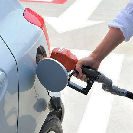
Allow the car to cool down, this will allow the computer, sensor or connection
to start working again. Drive to a gas station and add fuel, this can help if the
problem is a weak fuel pump by increasing the fuel level in the tank.
The ignition switch controls the electrical system to the engine and vehicle,
connections inside the switch can become overheated causing an electrical disconnect.
Once the connection has cooled, cycle the switch from on and off many times without
cranking the engine over. This can clean off the contacts and get the car running
again.

Turn the key on to see if the car has electrical power, the dash lights will be bright, dim or not on at all. If the dash lights are dim, or out you may have a bad or shorted battery or battery cable connection which is an easy fix. This video shows how to replace a battery and clean and tighten the battery cables.
A vehicle's fuel pump is used to supply the engine with gasoline, this pump uses an electric motor which can wear and fail intermittently, turn the ignition key on, you should hear a low hum in the rear of the car for about 5 seconds. If not try to use a large object like a piece of wood or a rock to smack the bottom of the fuel tank, this should get you going again. This also lets you know the fuel pump is bad and needs to be replaced. Watch the video below to see how to replace a typical fuel pump.
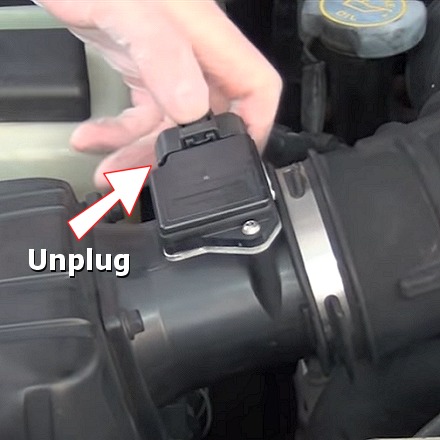
Most vehicles unitize a
mass air flow sensor
(MAF) which measures the air volume entering the engine. The problem occurs when
the sensor starts to fail, this is because it will report 0 air flow to the
engine computer, which
in turn shuts down the fuel system causing the engine to stall. Simply unplug the
sensor, this can get you going because the computer will now use a default value
while turning the fuel back on to the engine, if this works
replace the mass air
sensor when you get home.
A crankshaft position sensor is notorious for getting hot and failing, responsible for providing engine rotation feedback information to the car's computer when this sensor stops working fuel is then cut off to the fuel injectors making the engine stall. A crankshaft sensor usually takes about 20 minutes to change out, here is a video showing the job being done.
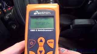
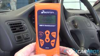
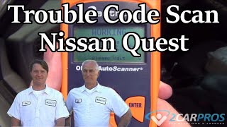
An engine code scanner can help identify the sensor or computer that is causing the stalling issue. These devices have become cheaper and easier to use than ever before. You can easily connect a code scanner which is inexpensive on Amazon (starting at $22.00), it will promptly reveal a single code or a series of codes. The lowest code number will be the most prudent, while the others may be a result of the engine stalling. For example; P0335, P0442 and P0700, the P0335 code is the lower of the three and is detecting a crankshaft position sensor that is failing. Please watch the following video to see how easy code gathering has become.
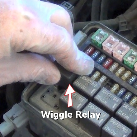
When a fuse or
relay becomes warm it can disconnect the electrical supply to a vital circuit
causing an engine stall. Many mechanics will employ the "wiggle test" to find such
a condition, with the engine running (idle) wiggle all main fuses and relays to
see if the engine stalls, if found remove
the fuse or
relay and look for signs of overheated or melted connections, then replace the
fuse or relay and enhance and clean the electrical terminals to fix the problem.
Car's today are designed with a CAN system (controller area network) which means many computers are talking together to enable engine and external controls will operate which can make diagnosing stalling problems tedious, but fear not, CAN scanners are now reasonably priced (starting at $35.00) on Amazon which will scan the entire car. Once the scan is complete, communication or trouble codes will promptly guide you to the problem.
Questions?
Our certified technicians are ready to answer stalling while driving questions for free. We hope you saved money and learned from this guide. We are creating a full set of car repair guides. Please subscribe to our 2CarPros YouTube channel and check back often for new videos which are uploaded regularly.
An engine that stalls while driving can be caused by a variety of issues. It’s a serious problem that can lead to dangerous situations on the road. In this guide, we’ll explore some common causes and their respective solutions.
1. Fuel System Issues
Fuel system issues are a common cause of engine stalling. These could be due to a clogged fuel filter, problems with the fuel pump, or a failing fuel injector.
How to Repair:
If you suspect a problem with your fuel system, consider the following steps:
- Replace the fuel filter: If it's clogged, the engine may not receive enough fuel, causing it to stall.
- Check the fuel pump: If the engine is not getting fuel, the pump may need to be replaced.
- Inspect the fuel injectors: If they're dirty or failing, have them professionally cleaned or replaced.
2. Ignition System Problems
Issues with your ignition system, like a faulty ignition coil or spark plugs, can cause your engine to stall.
How to Repair:
Follow these steps if you suspect an ignition system problem:
- Replace spark plugs: If they're old or faulty, they may not ignite the fuel properly.
- Check the ignition coil: A bad coil can lead to a loss of power or engine stalling.
3. Vacuum Leak
A vacuum leak can cause an engine to stall, often at idle or when the vehicle is decelerating.
How to Repair:
Here's how to address a vacuum leak:
- Inspect the engine for any visible signs of a leak, such as cracked or broken hoses.
- If you can't find a leak visually, consider having a mechanic conduct a smoke test.
4. Sensor Failures
Failure of sensors like the Mass Air Flow (MAF), Oxygen (O2), or throttle position sensor can cause an engine to stall.
How to Repair:
Here's how to tackle sensor failures:
- Use a code reader to check for error codes. This can help you identify which sensor may be causing the problem.
- Replace the faulty sensor. This is typically a straightforward process, but varies by vehicle.
5. Transmission Issues
If you're driving a manual car, a problem with the clutch could cause your engine to stall. For automatic cars, a failing torque converter could be the culprit.
How to Repair:
Follow these steps for transmission-related problems:
- Inspect the clutch: If it's worn or failing, it may need replacement.
- Check the torque converter: If your automatic car is stalling at low speeds or when coming to a stop, you may need a new torque converter.
Conclusion
While this guide gives you a good start on troubleshooting engine stalling, remember that serious or persistent issues should always be addressed by a professional mechanic. Your safety on the road is paramount.
Article published 2023-06-05
Code Read Retrieval/Clear Mercedes Benz
Code Read Retrieval/Clear Honda
Code Read Retrieval/Clear