Hi,
Here are the directions for removing and installing a 5-speed manual transmission from this vehicle. The attached pics correlate with the directions.
______________________________________
2001 Volkswagen Jetta GL Sedan (9M2) L4-2.0L (AVH)
Transmission Removing and Installing
Vehicle Transmission and Drivetrain Manual Transmission/Transaxle Service and Repair Procedures 5 Speed Manual 02J Transmission Removing and Installing
TRANSMISSION REMOVING AND INSTALLING
5 Speed Manual 02J
imageOpen In New TabZoom/Print
Special tools and equipment
- 10-222 A Support
- 10-222 A/1 Support
- V.A.G 1383A Transmission jack
- 3282 Transmission support
- 3282/8 Adjustment plate
- 3282/40 Pin (3x)
- 3282/59 Support
pic 1
Special tools and equipment
- 3300 A Engine support
- VW 457/1 Support rails
- 3336 Transmission lifting beam
Additionally for vehicles with 6-Cyl. Engines
- 10-222 A/3 Adapter
Modifying Support Rails VW 457/1
- Support rails VW 457/1 are required to remove and install the transmission.
Pic 2
To secure support rail VW 457/1 to the subframe a new hole is required.
Dimensions given are in mm.
- Drill an 8.5 mm (0.335 inch) diameter hole (arrow) in 5upport rail VW 457/1.
Removing
- Remove engine cover.
Note: Check whether a coded radio is installed as during the forthcoming work sequences the battery ground strap must be disconnected. Obtain radio code first if necessary.
- With ignition switched off disconnect battery ground strap.
Pic 3
- Remove intake hose -1 -, connector -2- and hose -3- from Mass Air Flow (MAF) Sensor.
- Remove complete air cleaner housing by unscrewing bolts -4- and -5-.
- Refer to; Powertrain Management.
Transmissions up to 05.99
pic 4
- Pull connector off vehicle speed sensor (arrow 1).
- Disconnect reverse light connector (arrow 2).
Pic 5
- Remove balance weight -A- and gear selector cable -B- from gear selector lever.
- Remove gear selector cable with washer and square nut (self-locking).
- Lift tab in direction of arrow and pull gate selector cable off actuating arm/relay lever -C-
pic 6
- Remove cable support bracket from transmission (arrows), if necessary unclip hose at cable support bracket first.
Pic 7
- Remove slave cylinder place to side and secure with wire, do not disconnect lines.
Note: Do not depress clutch pedal.
Pic 8
- Remove cable retainer (arrow -1-) on starter.
- Remove upper securing bolt (arrow -2-) on starter.
- Remove ground strap at engine/transmission upper securing bolt.
- Remove upper engine/transmission securing bolts.
- Remove engine/transmission upper securing bolts.
Transmissions from 05.99
pic 9
- Remove cable support bracket from transmission(arrows). If necessary unclip hose at cable support bracket first.
Pic 10
- Remove circlip and pull off gate selector cable -A- with relay lever.
- Remove nut (arrow) and remove gear selector cable -B- with transmission selector lever.
- Tie selector cable with transmission selector lever and gate selector cable with relay lever up.
Pic 11
- Disconnect connector from vehicle speed sensor (arrow 1).
- Disconnect reverse light connector (arrow 2).
Pic 12
- Remove slave cylinder and place to side, secured with wire. Do not disconnect hydraulic lines.
Note: Do not depress clutch pedal.
Pic 13
- Remove cable retainer (arrow 1) on starter.
- Remove wiring and cable from starter.
- Remove ground strap at engine/transmission upper securing bolt.
- Remove upper securing bolt (arrow 2) on starter.
- Remove engine/transmission upper securing bolts.
- If there are hoses and cable connections in area of engine mounting eye for support 1 0-222A, remove these now.
Pic 14
Continued for vehicles with 4-Cyl. Engine
- Fit support bar 1 0-222A together with legs 10222 A/1.
Pic 15
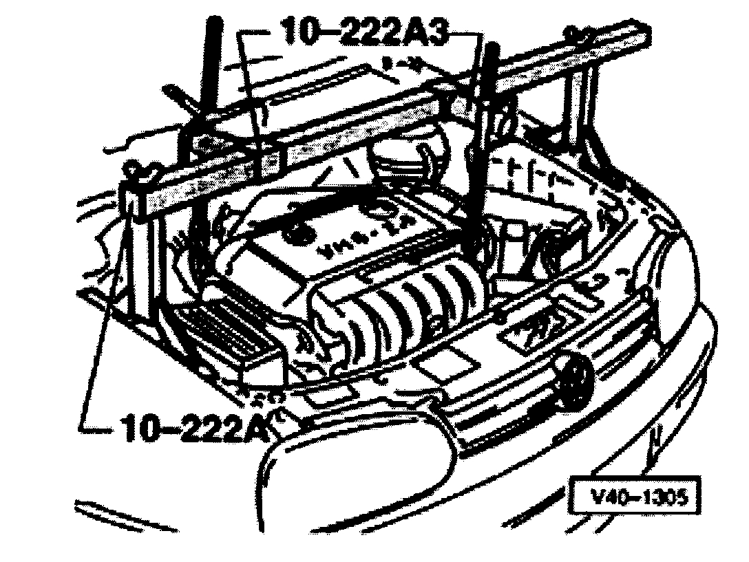
Continued for vehicles with 6-Cyl. Engines
- Fit support bar 10-222A together with legs 10222 A/1 and adapters 10-222 A/3.
Continued for all vehicles
- Take weight of engine/transmission assembly on spindles.
- If fitted, remove center and left part of insulation tray below engine/transmission.
- Remove power steering line from starter and transmission.
- Remove starter.
Refer to Starting and Charging.
- Remove right hand inner constant velocity joint protective cover from engine if fitted.
- Turn wheels fully onto left lock.
- Disconnect drive shafts from flanged shafts and tie up as high as possible. Do not damage surface protection of parts.
Pic 16
- Remove flywheel small cover plate -A- behind right-hand flanged shaft (arrows), if fitted.
- Remove lower flywheel cover plate, if part of original equipment.
- Separate exhaust system and if necessary remove from subframe.
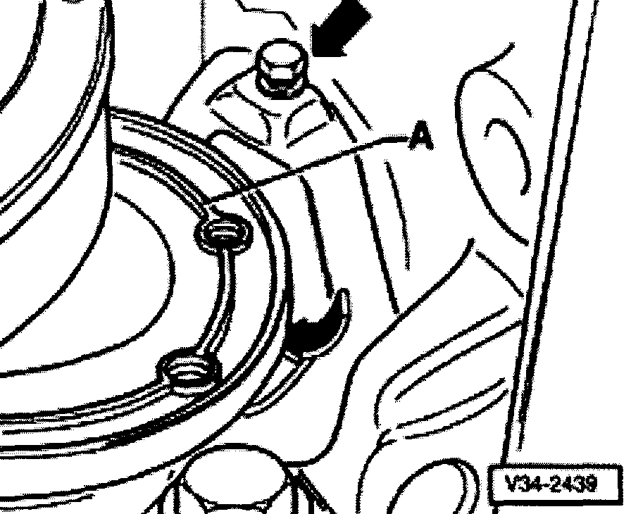
Pic 17
- Remove pendulum support (arrows A and B).
Pic 18
- Remove transmission support (arrow A) from transmission.
- Remove hex bolts (arrows B) from left-hand hand assembly mounting.
- Incline engine/transmission assembly by lowering it via left spindle of support bar 10-222A.
- The transmission mount -A- securing bolts (arrows) must be accessible.
Pic 19
- Remove transmission mount -A- (arrows).
Pic 20
- Bolt support rail VW 457/1 to both pendulum support securing holes on subframe.
- Insert spacers totaling 6 mm between subframe and support rail VW 457/1.
-A- Qty. 2 hex bolts M 8 x 25
- Fit support 3300 A and secure (arrows).
Pic 21
Vehicles with 5 valve engine
- Remove a lower engine/transmission securing bolt so that support 3300 A can be installed.
The support 3300 A must be installed directly next to the transmission on the engine.
Continued for all vehicles
- Press engine/transmission forward carefully.
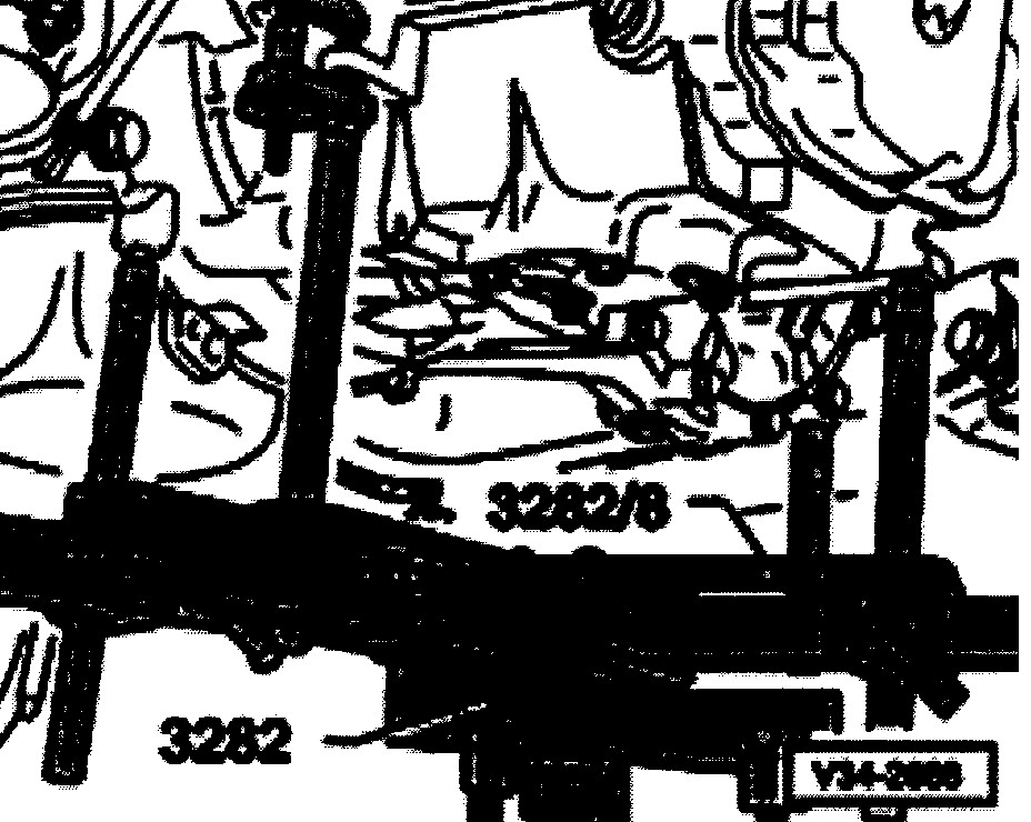
Note: Do not damage power steering line when moving engine/transmission assembly.
- Assemble transmission jack with transmission support 3282, adjustment plate 3282/8 for "02A" transmission and support elements as follows:
- Place adjustment plate 3282/8 on transmission support 3282 (adjustment plate only fits in one position).
- Align arms of transmission support according to holes in adjustment plate.
Pic 22
- Bolt support elements -A-, as illustrated, on adjustment plate.
Pic 23
- Place transmission jack under vehicle.
- Align adjustment plate parallel to transmission and lock safety supports on transmission.
- Remove lower engine/transmission securing bolts.
Pic 24
- Press transmission off dowels and carefully swing towards subframe.
- Lower transmission slightly and incline to left via spindles of transmission support 3282.
Pic 25
- Lower transmission carefully guiding right-hand flange shaft -A- in area of flywheel as illustrated. Guide left-hand flange shaft -B- in area of subframe.
Note:
- When lowering, change position of transmission using the transmission support 3282 spindles.
- Do not damage power steering line when lowering transmission.
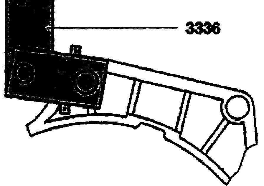
Transporting the transmission
pic 26
- Bolt transmission lifting device 3336 to clutch housing.
Pic 27
- Set support arm on sliding piece with locking pin (arrow).
No. Of holes visible = 5
- Lift transmission with workshop crane and transmission lifting device 3336.
- Place transmission, for example, onto transport container.
Installing
pic 28
Note:
- Before installing the transmission press the clutch release lever toward the transmission housing and secure it with an assembly pin, assembly bolt or a M 8 x 35 bolt. Remove it after the transmission has been installed. The hole will then be sealed by the 3rd cable support bracket securing bolt or plugged.
Pic 29
- When replacing a transmission, the sensors for the speedometer, gear selector and relay lever must be transferred to the new assembly.
- Clean input shaft splines and lightly grease with GOOD 100 grease.
The clutch plate must be able to slide lightly back and forth on the input shaft.
- Check whether dowel sleeves for aligning engine/transmission are fitted in cylinder block, install if necessary.
- Ensure that intermediate plate is correctly positioned on engine.
Pic 30
- Bolt support rail VW 457/1 to both pendulum support securing holes on subframe.
- Insert spacers totaling 6 mm between subframe and support rail VW 457/1.
-A- Qty. 2 hex bolts M 8 x 25
- Fit support 3300 A and secure (arrows).
Pic 31
Vehicles with 5 valve engine
The support 3300 A must sit on the threaded boss on the engine.
Continued for all vehicles
- Press engine forward carefully.
Note: Do not damage power steering line.
- Assemble transmission jack with transmission support 3282, adjustment plate 3282/8 for "02A" transmission and support elements as follows:
- Place adjustment plate 3282/8 on transmission support 3282. (Adjustment plate only fits in one position).
- Align arms of transmission support according to holes in adjustment plate.
Pic 32
- Bolt on support elements -A-, as illustrated, on adjustment plate.
- Place transmission on transmission jack.
- Align adjustment plate and transmission parallel with one another and lock safety supports on transmission.
Pic 33
- Place transmission jack under vehicle, arrow symbol -B- (= Illustration V34-2670) on adjustment plate points to front of vehicle.
- Incline transmission to left via spindles of transmission mounting 3282.
- Insert transmission.
Note: Do not damage power steering line.
- Install lower engine/transmission securing bolts.
Pic 34
- Remove support 3300 A (arrows).
- Remove bolts -A- and remove support rail VW 457/1.
- Install upper engine/transmission securing bolts.
Pic 35
- Install transmission mount -A- with new bolts (arrows).
- Align engine/transmission in installation position.
Pic 36
- Install new hex bolts (arrows -B-)for left hand assembly mounting in transmission mounting.
- Mount transmission support (arrows -A-) to transmission.
WARNING: Do not remove support bar 10-222A until the bolts securing the left-hand transmission mount have been tightened to torque setting.
Pic 37
- Install lower engine/transmission securing bolt (arrow A).
- Install pendulum support (arrows). Use new bolts for securing.
- Reconnect exhaust system.
- Install retainer for power steering line on starter and on transmission.
Pic 38
- If removed, install small cover plate -A- behind right-hand drive flange (arrows).
- If removed, install large cover plate for clutch.
- Fit drive shafts to transmission.
- If removed, install protective cap for right-hand inner constant velocity joint to engine.
- Install starter.
Pic 39
- Install slave cylinder.
Pic 40
- Install cable support bracket on transmission (arrows), if necessary push hose onto cable support bracket.
Transmissions up to 05.99
pic 42
- Install gear selector cable -B- and balance weight -A- on gear selector lever.
- Lift tab in direction of arrow and fit gate selector cable on follower/relay lever -C-.
Pic 43
- Attach reverse light connector (arrow 2). Attach all other electrical connections and ground wires to transmission and to engine/transmission securing bolts.
- Attach connector to speedometer sensor (arrow 1).
- Assemble air intake duct.
- Reconnect ground strap to battery.
Note: Note radio coding for vehicles with coded radio.
- Check transmission oil.
- Adjust gear selector mechanism.
- Install engine cover.
- Install insulation tray below engine/transmission, if fitted.
Transmission from 05.99
pic 44
- Fit gear selector cable -B- with transmission selector lever (arrow).
- Fit gate selector cable -A- with relay lever and secure (arrow).
Pic 45
- Attach reverse light connector (arrow 2). Attach all other electrical connections and ground wires to transmission and to engine/transmission securing bolts.
- Attach connector to speedometer sensor (arrow
- Assemble air intake duct.
- Reconnect ground strap to battery.
Note: Note radio coding for vehicles with coded radio.
- Check transmission oil.
- Adjust gear selector mechanism.
- Install engine cover.
- Install insulation tray below engine/transmission, if fitted.
Continued for all vehicles
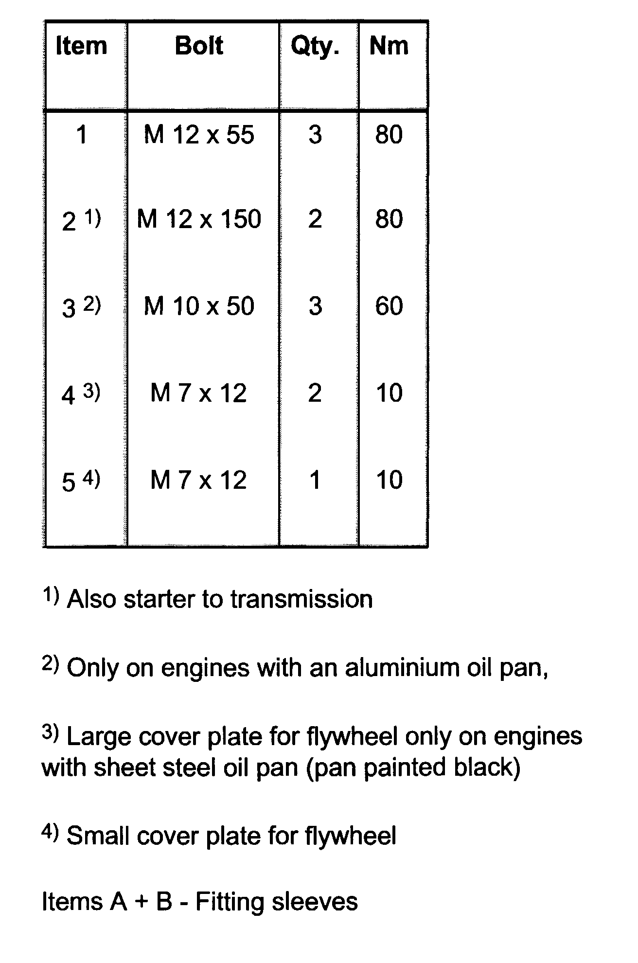
Tightening torques
Transmission to engine
pic 46
pic 47
Vehicles with 4-Cyl. Engine
1. Also starter to transmission
2. Only on engines with an aluminum oil pan,
3. Large cover plate for flywheel only on engines with sheet steel oil pan (pan painted black)
4. Small cover plate for flywheel
Items A + B - Fitting sleeves
pic 48
pic 49
Vehicles with 6-Cyl. Engine
1. Also starter to transmission
2. Only on engines with an aluminum oil pan, on some engines M 10 x 50 bolts are tiffed and the tightening torque is 25 Nm.
3. Flywheel cover plate only on engines with a sheet steel oil pan (pan painted black)
Items A + B - Fitting sleeves
pic 50
Transmission mount -A- to transmission 50 Nm + 90°
- Replace bolts.
Pic 51
Transmission to body
Bolts -A- 25 Nm
Bolts-B- 100 Nm
pic 52
Rear transmission mounting
Bolts -A- 20 Nm + 90°
Bolts-B- 40 Nm + 90°
- Replace bolts
Note: Install engine transmission mountings stress free.
Selector cable support bracket to transmission 25 Nm
Selector cable bolt to transmission selector lever 25 Nm
Balance weight to transmission selector lever 25 Nm
Transmission selector lever to transmission 20 Nm
______________________________________
I hope this is helpful. Let me know if you have other questions.
Take care,
Joe
Images (Click to make bigger)
Wednesday, November 11th, 2020 AT 5:52 PM