Hi and thanks for using 2CarPros. Com.
This is not an easy one. The first set of directions are for removal. The first 29 pictures correlate with the removal directions.
______________________________________
Transmission Removal
Vehicle Transmission and Drivetrain Manual Transmission/Transaxle Service and Repair Procedures Transmission Removal
TRANSMISSION REMOVAL
Transmission Removal
Special Tools Required
Engine hanger/adapter VSB02C000015 *
Engine support hanger, A & Reds AAR-T-12566 *
Subframe adapter VSB02C000016 *
* Available through the Honda Tool and Equipment Program 888-424-6857.
NOTE: Use fender covers to avoid damaging painted surfaces.
1. Make sure you have the anti-theft codes for the radio and the navigation system, then write down the customer's radio station presets.
2. Set the wheels in straight ahead position.
3. Lock the steering wheel.
4. Disconnect the negative (-) cable first, then the positive (+) cable from the battery. Remove the battery.
5. Remove the air cleaner housing.
6. Remove the battery base.
7. Carefully remove the slave cylinder without bending the clutch line. Do not operate the clutch pedal once the slave cylinder has been removed.
Type A
Type B
8. Remove the cable bracket (A), then disconnect the cables (B) from the top of the transmission housing. Carefully remove both cables and the bracket together to avoid bending the cables.
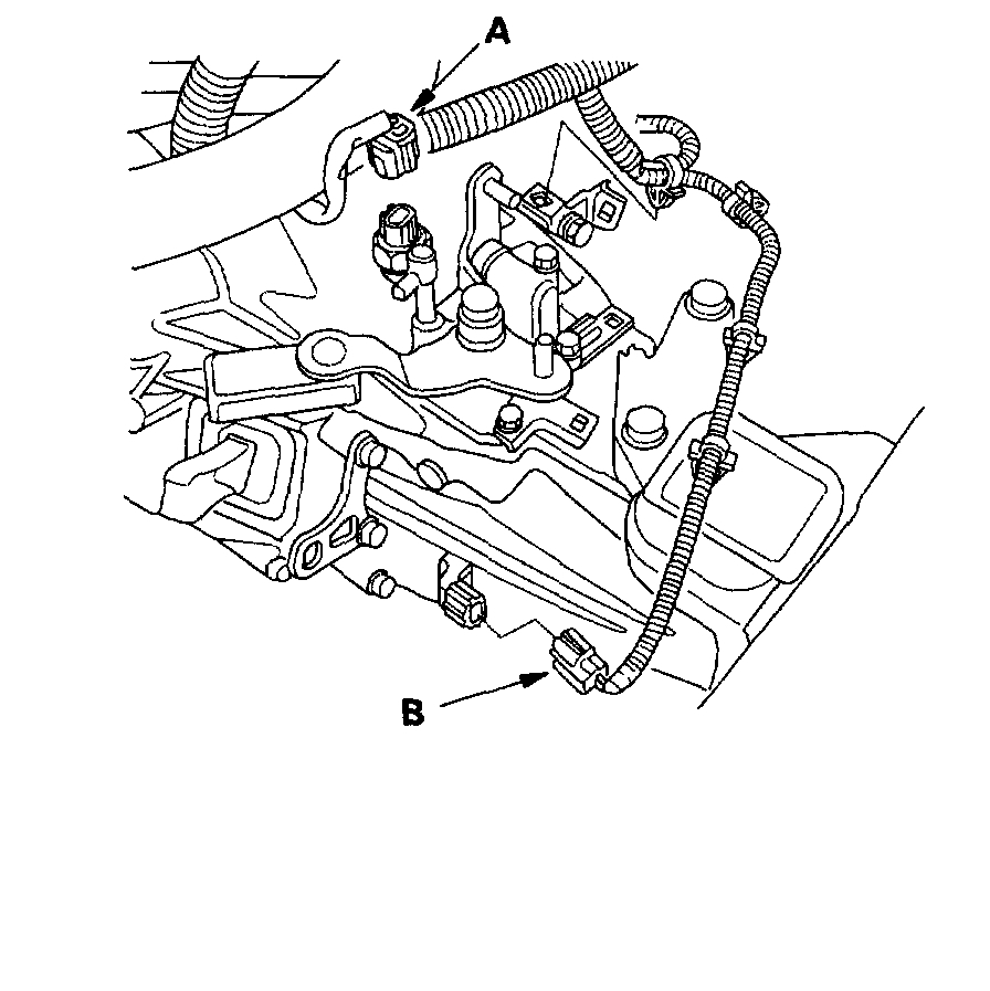
9. Disconnect the output shaft (countershaft) speed sensor connector (A) and back-up light switch connector (B).
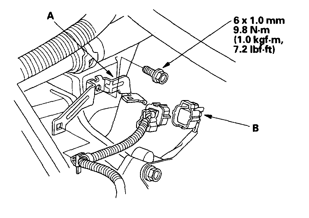
10. Disconnect the secondary heated oxygen sensor (secondary HO2S) connector (A), then remove the bracket (B).
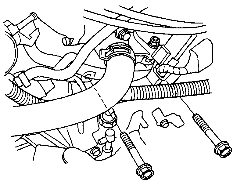
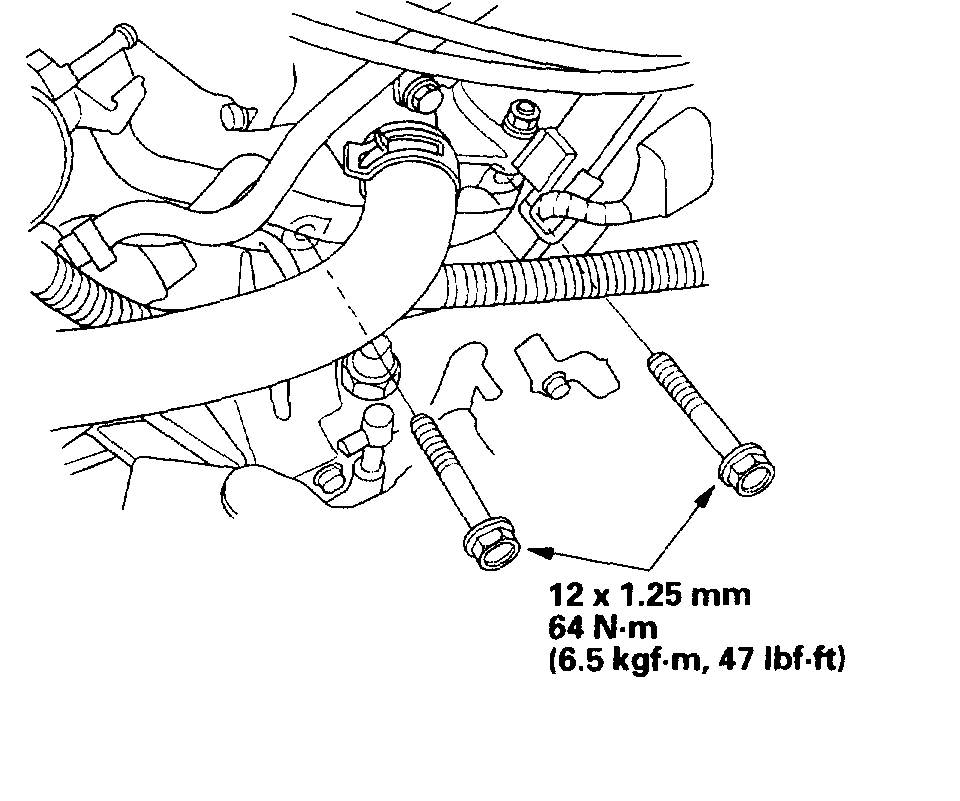
11. Remove the front mount stop (A), then remove the front mount bolt (B).
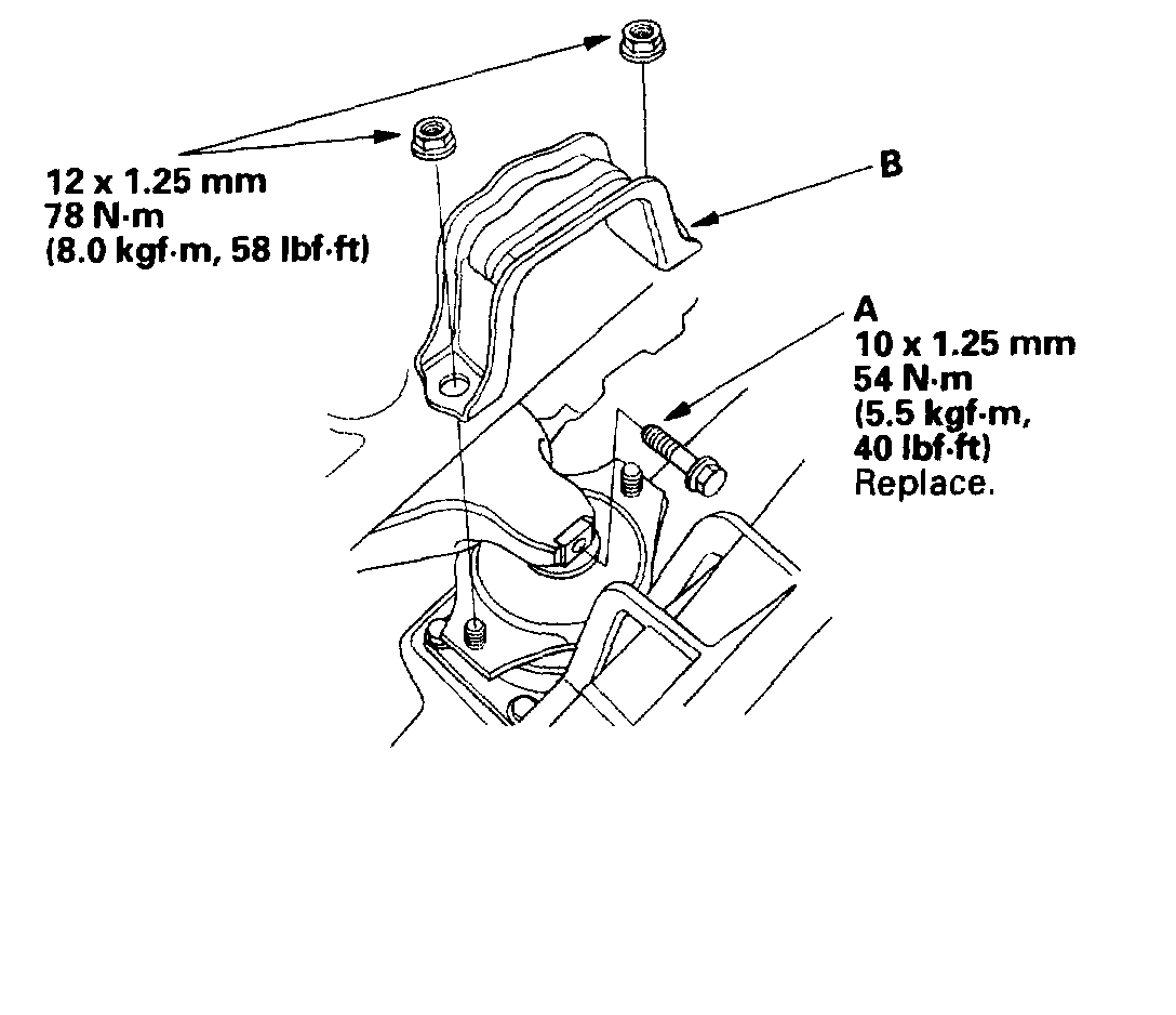
12. Remove the rear mount stop.
13. Remove the transmission upper mounting bolts.
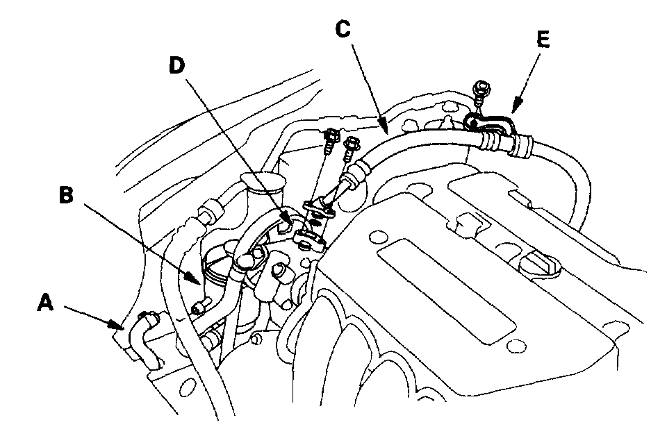
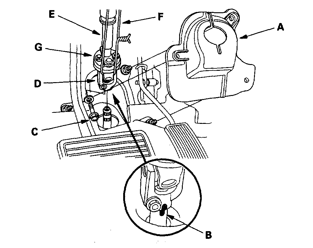
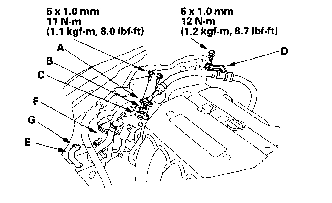
14. Remove and plug the return hose (A) from the power steering fluid reserver (B). Wipe off any spilled fluid once.
15. Remove the power steering pump outlet line (C) from the power steering pump (D).
16. Remove the power steering pump outlet line bracket (E).
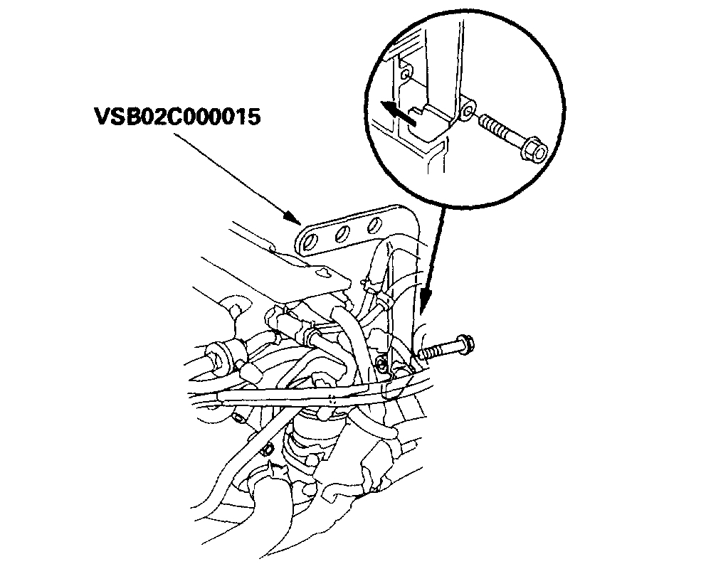
17. Attach the special tool to the threaded hole in the cylinder head.
18. Install the engine support hanger (AAR-T-12566) to the vehicle, and attach the hook (A) to the special tool adapter (B). Tighten the wing nut (C) by hand, and lift and support the engine.
19. Remove the transmission mount bracket (A) and ground cable (B).
20. Remove the steering joint cover (A).
21. Make a reference mark (B) across the steering joint and steering gearbox pinion shaft. Remove the steering joint bolt (C), and disconnect the steering joint (D) by removing the steering joint toward the steering column. Hold the slider shaft (E) on the column with a piece of wire (F) between the joint yoke (G) on the slider shaft to the joint yoke on the upper shaft.
22. Raise the vehicle, and make sure it is securely supported.
23. Remove the front wheels.
24. Drain the transmission fluid. Reinstall the drain bolt using a new washer.
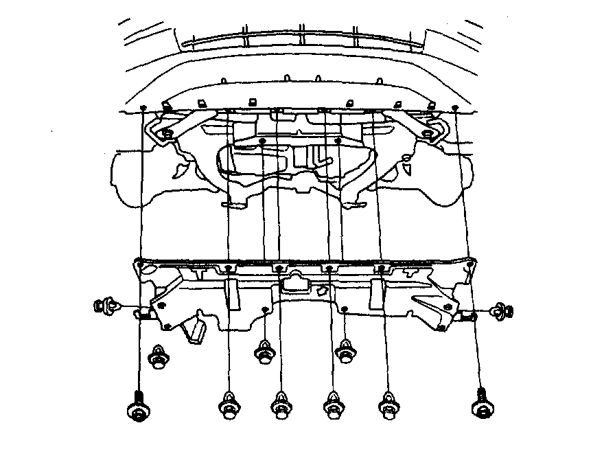
25. Remove the splash shield.
26. Separate the tie-rod ball joint.
27. Separate the front stabilizer link.
28. Remove the damper fork.
29. Separate the knuckle from the lower arm.
30. Disconnect the power steering pressure switch connector.
31. Remove exhaust pipe A.
32. Remove the heat shield.
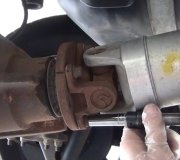
33. Remove the inboard joint of driveshafts.
34. Remove the intermediate shaft.
35. Remove the engine lower rear mount mounting bolts.
36. Remove the transmission lower mount mounting nuts.
37. Remove the middle subframe mounting bolts.
38. Make the appropriate reference lines (A) at both ends of the subframe (B) that line up with the edge (C) of the stiffeners (D).
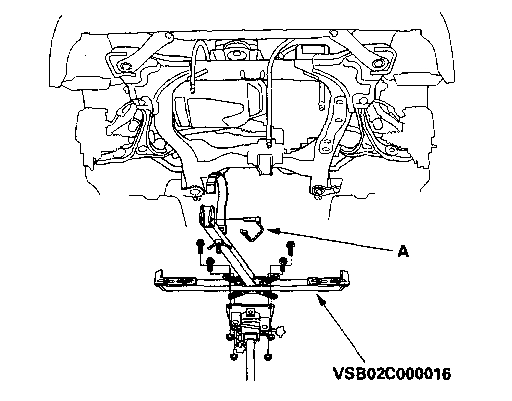
39. Attach the special tool to the subframe by wrapping the band over the subframe and attaching the end of the band to the tool with a pin (A).
40. Raise the jack and line up the slots in the arms with the bolt holes on the corner of the jack base (B), then attach them securely.
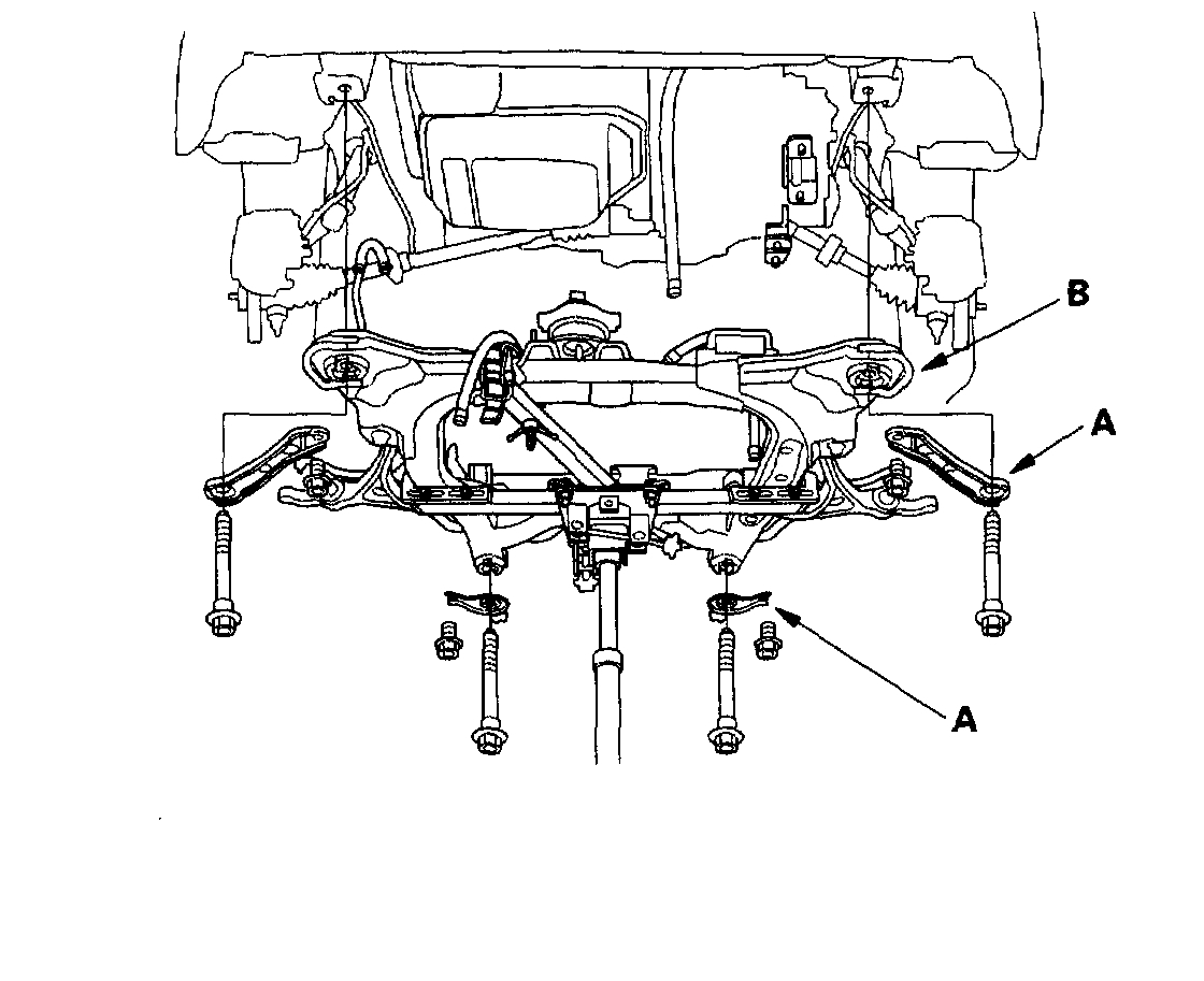
41. Remove the front suspension, subframe stays (A) and front suspension subframe (B).
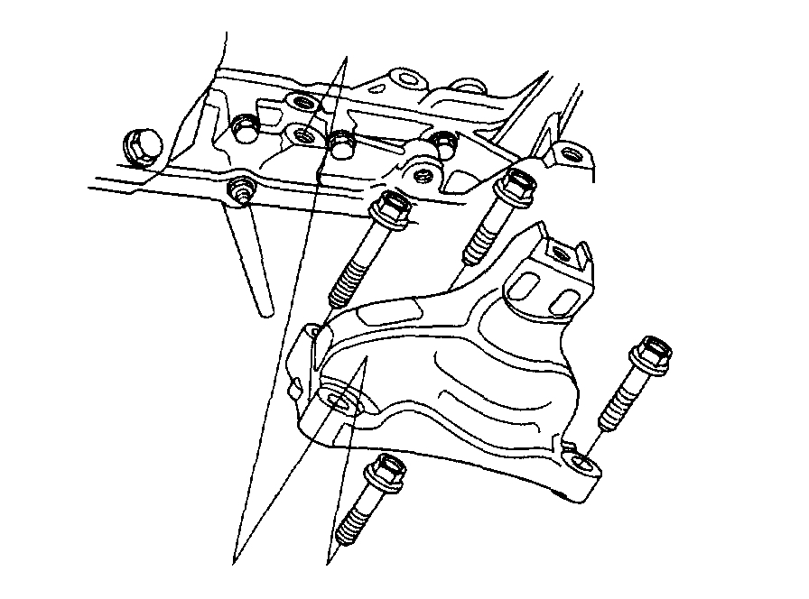
42. Remove the front engine mount upper bracket.
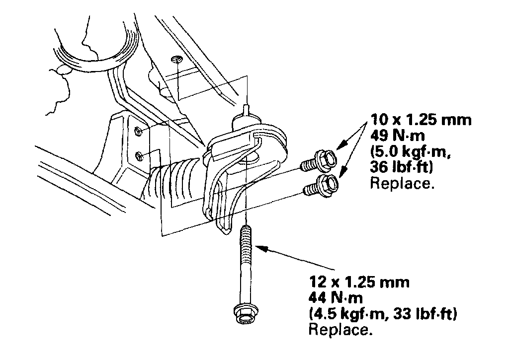
43. Remove the shift cable bracket (A), rear engine mount upper mounting bolt (B) and rear engine mount (C).
44. Remove the rear engine mount upper bracket.
45. Remove the clutch cover
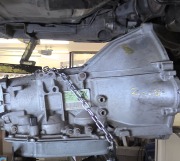
46. Place the transmission jack under the transmission, and remove the transmission lower mounting bolts.
47. Pull the transmission away from the engine until the transmission mainshaft clears the clutch pressure plate, then lower the transmission on the transmission jack.
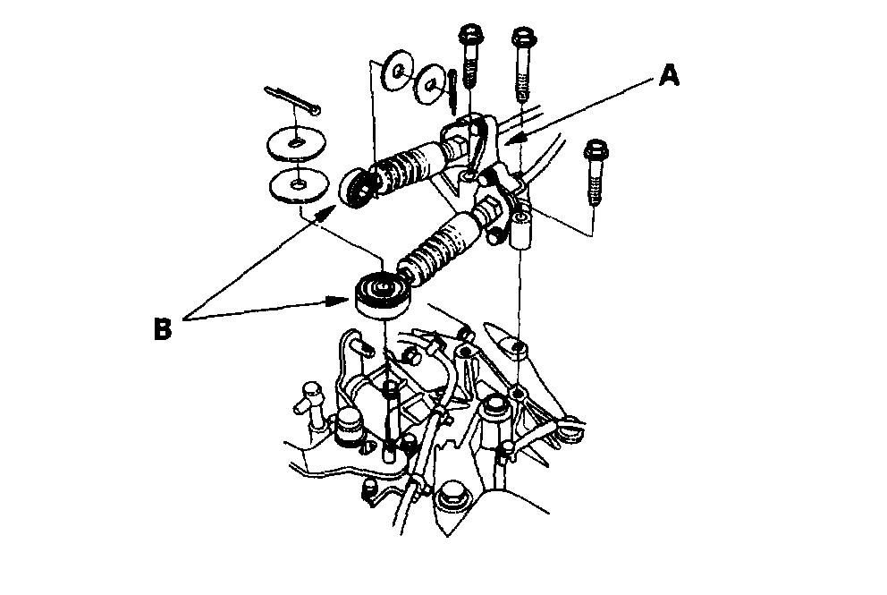
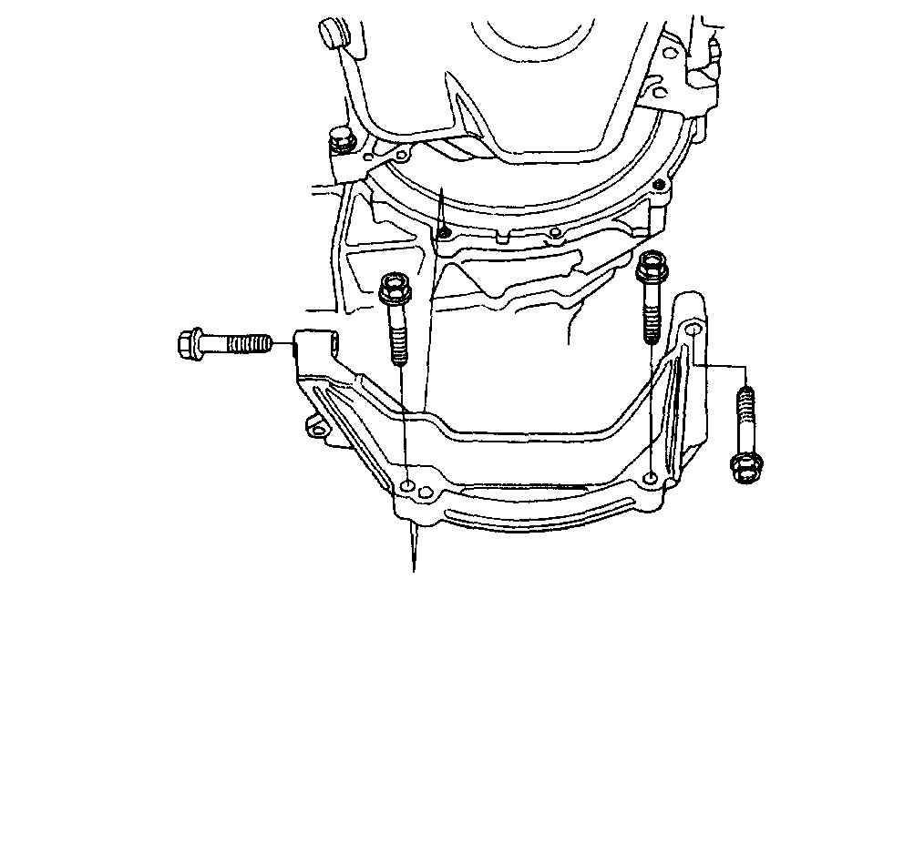
48. Remove the transmission lower front mount (A) and transmission lower rear mount (B).
49. Remove the release fork boot (A) from the clutch housing (B).
50. Remove the release fork (C) from the clutch housing by squeezing the release fork set spring (D) with pliers. Remove the release bearing (E).
______________________________________________________________________________________
2003 Honda Accord L4-2.4L
Transmission Installation
Vehicle Transmission and Drivetrain Manual Transmission/Transaxle Service and Repair Procedures Transmission Installation
TRANSMISSION INSTALLATION
Transmission Installation
Special Tools Required
Engine hanger/adapter VSB02C000015
Engine support hanger, A & Reds AAR-T-12566 *
Subframe adapter VSB02C000016 *
* Available through the Honda Tool and Equipment Program 888-424-6857.
SRS components are located in this area. Review the SRS component locations, and the Precautions and Procedures before doing repairs or service.
1. Check that the two dowel pins are installed in the clutch housing.
2. Apply super high temp urea grease (P/N 08798-9002) to the release fork (A) and the release bearing (B). Install the release fork, the release bearing, and the boot (C)
3. Install the transmission lower front mount (A) and transmission lower rear mount (B).
4. Place the transmission on the transmission jack, and raise it to the engine level.
5. Install the transmission mounting lower bolts.
6. Install the clutch cover.
7. Install the rear engine mount upper bracket.
8. Install the rear engine mount (A), rear engine mount upper mounting bolt (B), and shift cable bracket (C).
9. Install the front engine mount upper bracket.
10. Support the subframe with the subframe adapter and a jack.
11. Install the front suspension subframe (A) and front suspension subframe stays (B).
12. Align the reference marks (A) with edge (B) of both rear stiffer (C), and tighten the rear subframe mounting bolts, then front bolts, and tighten the stiffener bolts to the specified torque.
13. Install the middle subframe mounting bolts.
14. Install the transmission lower mount mounting nuts.
15. Install the engine lower rear mount mounting bolts.
16. Install the intermediate shaft.
17. Install the inboard joint of driveshafts.
18. Install the heat shield.
19. Install the knuckle onto the lower arm.
20. Install the damper fork.
21. Connect the front stabilizer.
22. Install the exhaust pipe A, mount (B), and new gaskets (C).
23. Connect the power steering pressure switch connector.
24. Connect the return line to the power steering fluid reservoir.
25. Install the tie-rod ball joint.
26. Install the splash shield.
27. Refill the transmission with fluid.
28. Install the front wheels, and set them in the straight ahead position.
29. Lower the vehicle.
30. Unlock the steering wheel.
31. Connect the steering joint to the steering gearbox pinion shaft (A) by aligning the reference mark (B), and remove the wire (C) from the joint yoke (D).
32. Install the steering joint cover (E).
33. Install the transmission mount bracket (A) and ground cable (B).
34. Remove the engine hanger and special tool from engine.
35. Install the power steering pump outlet line (A) with a new O-ring (B) to the pump (C), and secure the hose clamp (D) with the bolt.
36. Connect the return the hose (E) to the power steering fluid reservoir (F), then secure the hose with is clamp (G).
37. Install the transmission upper mounting bolts.
38. Install the rear mount stop.
39. Install the engine front mount mounting bolt (A) and front mount stop (B).
40. Install the bracket (A), then connect the secondary heated oxygen sensor (secondary HO2S) connector (B).
41. Connect the back-up light switch connector (A) and output shaft (countershaft) speed sensor connector (B).
42. Install the cable bracket (A) and cables (B).
43. Apply a light coat of super high temp urea grease (P/N 08798-9002) to the cable ends, and install new cotter pins (C).
44. Apply super high tamp urea grease (P/N 08798-9002) to the end of the cylinder rod. Install the slave cylinder. Take care not to bend the clutch line.
Type A
Type B
45. Install the battery base.
46. Install the air cleaner housing.
47. Remove the steering wheel.
48. Center the cable reel by first rotating it clockwise until it stops. Then rotate it counterclockwise (about three full turns) until the arrow mark on the label points straight up.
49. Reinstall the steering wheel.
50. Install the battery. Connect the positive (+) cable first, then the negative (-) cable to the battery.
51. Fill the power steering fluid reservoir with fluid to the upper level line.
52. Start the engine, and run it at fast idle, then turn the steering wheel from lock-to-lock several times to bleed air from the system.
53. Recheck the fluid level, and refill if necessary.
54. Check the front wheel alignment.
55. Check the steering wheel spoke angle. If the steering spoke angles to the right and left are not equal (steering wheel and rack are not centered), correct the engagement of the joint/pinion shaft serrations, then adjust the front toe by turning the tie-rod ends if necessary. If you need to correct the engagement of the joint/pinion shaft, repeat steps 47 thru 49 after disconnecting the battery and waiting 3 minutes.
56. Test-drive the vehicle.
57. Check the clutch operation.
58. Enter the anti-theft code for the radio and navigation system, then enter the customer's radio station presets.
____________________________________________________________________________________
Starting with picture 30 the remaining pictures correlate with the replacement.
I hope this helps. Let me know if you have other questions.
Take care,
Joe
Images (Click to make bigger)
SPONSORED LINKS
Monday, August 20th, 2018 AT 7:54 PM