It sure sounds like the crankshaft angle sensor is bad. I would try replacing it they go bad all of the time.
Here is a the Denso sensor on Amazon for $53.00
https://www.amazon.com/gp/product/B00PYQB40A/ref=as_li_qf_sp_asin_il_tl?ie=UTF8&tag=2carprcom-20&camp=1789&creative=9325&linkCode=as2&creativeASIN=B00PYQB40A&linkId=3bc24fda11629fb9ea31f9aa822f7a32
Here is some testing guides from the book:
Real Fixes
Component Tests
Common Replaced Parts
0k25k50k75k100k125k150k175k200k012
ignition control module...
distributor rotor (1)
ignition coil (1)
ignition distributor ca...
spark plug (1)
ENGINE DOES NOT START, REPLACED IGNITION CONTROL MODULE
Complaint
The customer states the engine will not start.
Cause
Confirmed the customer's complaint and found the engine did not start. Performed a visual inspection of the fuel system and ignition system components, but found no obvious faults. Removed the spark plugs and performed a visual inspection, but found no obvious faults. Connected an inline spark tester to the ignition coil secondary lead, started the engine, and found the spark was intermittent. Used a multi-meter to measure the resistance of the ignition coil and found the measured resistance was within specifications. Connected a lab scope to the ignition coil primary signal circuit, started the engine and found an erratic signal. Performed a visual inspection of the ignition control module wiring harness and connector terminals, but found no obvious faults. Key on, engine off, used the multi-meter to check for voltage and ground at the ignition control module and found both were present. Connected the lab scope to the ignition control module primary signal trigger input, started the engine and found the waveform revealed no faults with the primary trigger. This indicated the ignition control module was faulty.
Correction
Replaced the ignition control module and verified the vehicle operated properly. The customer's concern did not return.
Real Fixes
Fixed It!
Engine Does Not Start, Replaced Ignition Control Module
51?
The customer states the engine will not start. Confirmed the customer's complaint and found the...
Engine Does Not Start, Replaced Ignition Coil, Ignition Control Module
The customer states the engine will not start. Confirmed the customer's complaint and found the...
Engine Does Not Start, Replaced Fuel Pump, Fuel Pump Relay
The customer states the engine will not start. Confirmed the customer's complaint and found the...
Engine Does Not Start, Replaced Ignition Coil, Ignition Control Module
The customer states the engine will not start. Confirmed the customer's complaint and found the...
Component Tests
Ignition Tests -> Carbureted/Fuel Injection
Tests
Koec Test
KOEC test is best used for diagnosing no start, no spark condition.
Connect test leads at ignition coil:
Yellow=coil(-)
Black=known good ground.
KOEO, primary ignition voltage must be present to continue with test.
Crank Engine and check for ICM switching at ignition coil while cranking.
As ICM switches, primary voltage spikes can be seen.
Resistance Test
Secondary ignition wire resistance
Connect ohmmeter
Red=either end of plug wire
Blue=other end of plug wire
Read amount of resistance:
10k ohms per foot or
25k ohms total resistance per wire.
Ignition Tests -> Fuel Injection
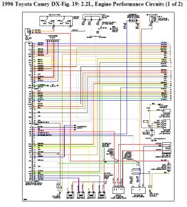
Location
Type: conventional
Best test Location:
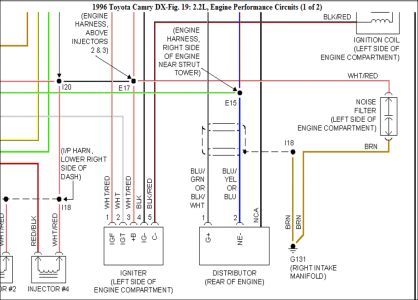
Distributor, coil, and igniter terminals.
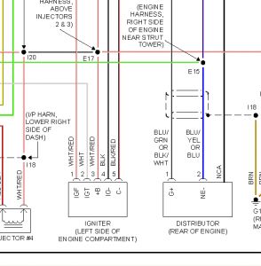
Component Location:
Distributor: at rear of CYL head.
Coil and igniter: at left rear of Engine compartment near brake booster.
CYL #1 Location:
(front of vehicle) firing order 1-3-4-2distributor rotates counter-clockwise
Tests
Out Of Range No Sig Test
Connect test leads:
Yellow=coil(-)
Black=known good
Ground.
Key on, primary IGN
Voltage should be
Present.
Move test leads:
Yellow=coil(+)
Black=known good
Ground.
Key on, primary IGN
Voltage should be
Present.
Ignition Tests -> Fuel Injection/Carbureted
Operation
System is conventional ignition using one ignition coil to produce high voltage for all cylinders.
Primary windings create a magnetic field that when collapsed across secondary windings, create high voltage.
This high voltage is required to overcome the greatest KV requirement in the secondary (normally the spark plug gap) this high voltage is transmitted from the coil to the spark plugs through a coil wire, dist cap, rotor and spark plug wires.
Tests
Secondary Ignition Test
Component Test Meter can be used to view secondary ignition waveforms.
CH1=Yellow secondary coil adapter.
GND=Black secondary coil adapter lead.
Black clip=known good ground.
Note: See LAB scope plug-in manual for proper hook up information.
Sweep , scale and delay may need to be adjusted depending on engine RPM and firing voltage.
Current Ramp Test
Ignition coil current can be checked using Component Test Meter & a low amp current Probe.
Connect current Probe to Component Test Meter as shown.
Perform auto zero adjustment before any measurements. This adjustment should be done prior to clamping Probe around any wire.
Press the auto zero button to zero Probe.
Clamp current Probe around the b+ side or the Control side of ignition coil. Do not clamp around both.
If coil is difficult to access, it may be possible to check coil current at the fuse box, if applicable.
Verify that Probe jaws are fully closed. If a negative waveform appears,open jaws & clamp Probe in other direction.
Ignition coil waveform should have a gradual rise or ramp as current begins to flow.
If vehicle is DIS equipped, current flow through each coil should be about the same.
If not, suspect resistance in power supply or ground circuits,or possible aftermarket assy not matched with OEM units.
If coil waveform has a sharp rise at the begining of the ramp upward, suspect shorted coil windings.
i have sure track a data base you type code symptoms etc in and this is what came up i know the ignition control module tested good on there machine but thats what came up on sure track.
Please let us know
Aug 27, 2015 at 9:44 PM
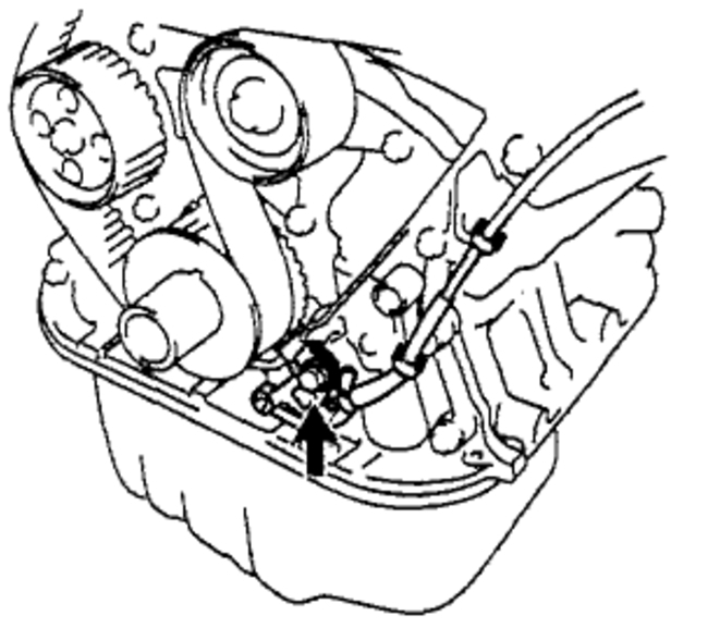
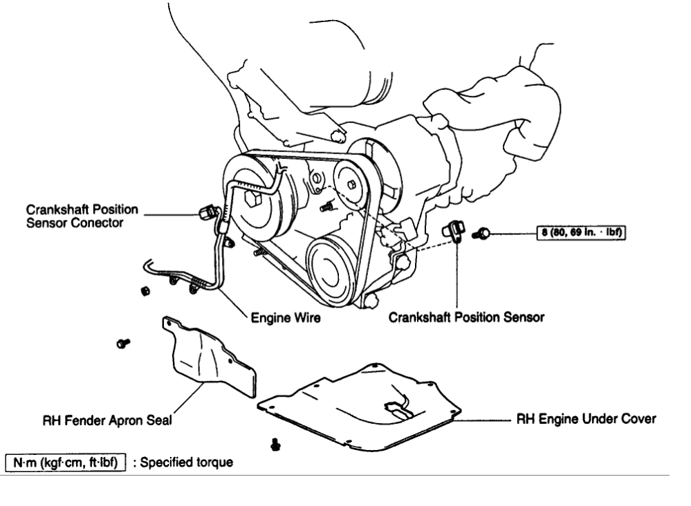

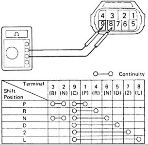
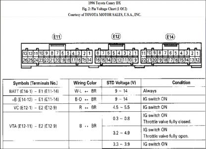
 Using an ohmmeter, measure the resistance between terminals.
Resistance:
Cold: 985 - 1,600 Ohms
Hot: 1,265 - 1,890 Ohms
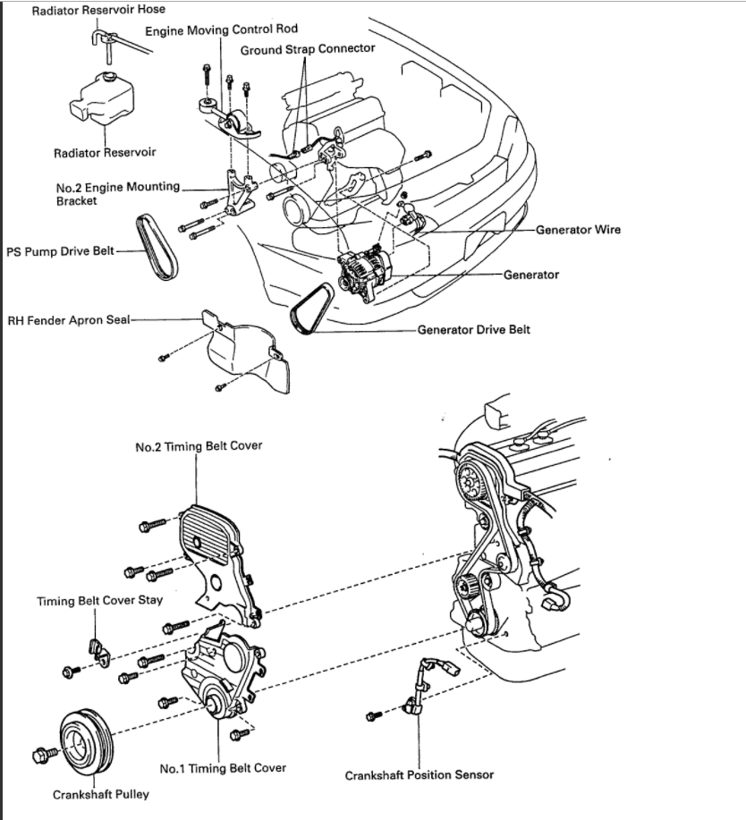
If the resistance is not as specified, replace the crankshaft position sensor.
RECONNECT CRANKSHAFT POSITION SENSOR CONNECTOR
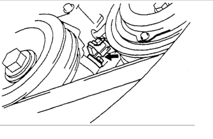
Using an ohmmeter, measure the resistance between terminals.
Resistance:
Cold: 985 - 1,600 Ohms
Hot: 1,265 - 1,890 Ohms
If the resistance is not as specified, replace the crankshaft position sensor.
RECONNECT CRANKSHAFT POSITION SENSOR CONNECTOR