Hi and thanks for using 2CarPros.
There are a few things which can cause no heat. For example, a plugged heater core, bad heater control valve, or (and most often) a blend air door actuator. Take a look at this link:
https://www.2carpros.com/articles/car-heater-not-working
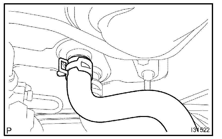
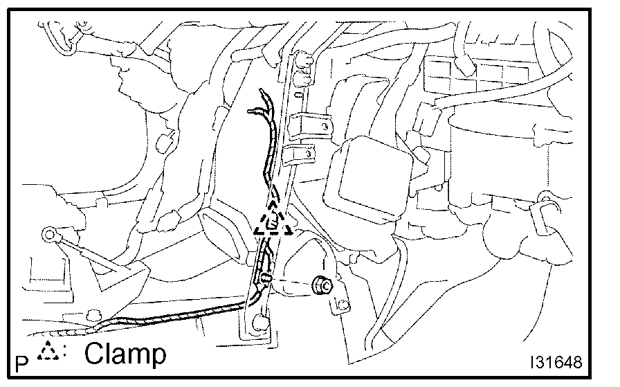
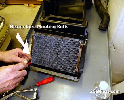
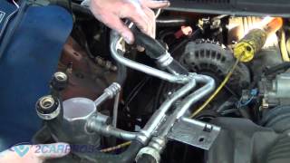
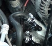
The actuator determines if you get heat or AC into the vehicle. Now, what I suggest is this. Start the engine and turn the heater on high. Allow the engine to warm up to operating temperature and turn it off. Next, locate the two heater core hose which will run from the engine to the firewall under the hood. Feel both. They should both be hot. If one is hot and the other cold, the heater core may be plugged. Take a look at picture 1. It shows the heater core return line at the firewall. There will be another hose that looks just like it which will be the supply. Do what I said. If one is hot and the other cold, you can try to flush the core. Basically, you remove both the supply and return heater core hoses and see if you can get water from a garden hose to run through it. If you can't here are the directions for replacing the heater core. Note: After these directions, I will provide directions for checking the blend air door as well as replacement if you find it bad. These are very extensive. However, they also indicate how to remove and replace the air mix actuator (blend air door actuator).
The directions include work to the AC unit because they work from the same location and one needs removed to access the other.
____________________________________
PROCEDURES
Air Conditioning Radiator Assy
Air Conditioning Radiator Assy
AIR CONDITIONING RADIATOR ASSEMBLY
OVERHAUL
1. DISCHARGE REFRIGERANT FROM REFRIGERATION SYSTEM
SST 07110-58060 (07117-58080, 07117-58090, 07117-78050, 07117-88060,07117-88070, 07117-88080)
2. DISCONNECT COOLER REFRIGERANT SUCTION HOSE NO.1
a. Install SST to piping clamp.
SST 09870-00015
HINT: Confirm the direction of the piping clamp claw and SST using the illustration showing on the caution label.
b. Push down SST and release the clamp lock.
NOTE: Be careful not to deform the tube, when pushing SST.
c. Pull SST slightly and push the release lever, then remove the piping clamp with SST.
d. Disconnect the cooler refrigerant suction hose No.1.
NOTE:
- Do not use tools like screwdriver to remove the tube.
- Cap the open fittings immediately to keep moisture or dirt out of the system.
3. DISCONNECT COOLER REFRIGERANT LIQUID PIPE A
SST 09870-00025
HINT: Disconnect cooler refrigerant liquid pipe A in the same way as the cooler refrigerant suction hose No.1.
4. DISCONNECT HEATER OUTLET WATER HOSE
a. Using pliers, grip the claws of clip and slide the clip and disconnect the heater outlet water hose.
5. DISCONNECT HEATER INLET WATER HOSE
HINT: Disconnect in the same way as the heater outlet water hose.
6. REMOVE INSTRUMENT PANEL SAFETY PAD SUB-ASSEMBLY
HINT: Refer to the instructions for removal of the instrument panel safety pad sub-assembly.
7. REMOVE AIR DUCT REAR NO.1
a. Remove the 2 screws, bolt and nut.
b. Remove the air duct rear No.1.
8. REMOVE AIR DUCT REAR NO.2
a. Remove the bolt and nut.
b. A/X models:
Remove the 2 screws, air duct rear No.2 and console box mounting bracket No.1.
c. M/X models:
Remove the screw, air duct rear No.2 and console box mounting bracket No.1.
9. REMOVE CONSOLE BOX DUCT NO.1 (AUTO AIR CONDITIONING)
a. Remove the clip and console box duct No.1.
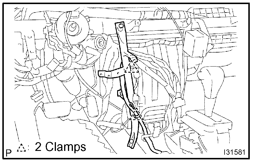
10. DISCONNECT FLOOR SHIFT PARKING LOCK CABLE ASSEMBLY
11. REMOVE WINDSHIELD WIPER RELAY ASSEMBLY
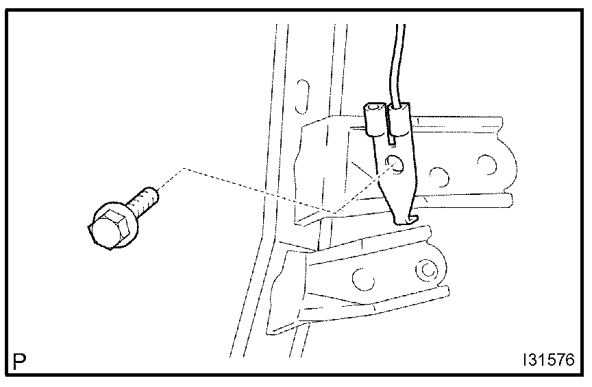
12. REMOVE INSTRUMENT PANEL BRACE SUB-ASSEMBLY NO.1
a. Remove the 2 bolts and 2 earth wires.
b. Release the 2 clamps.
c. Remove the bolt and screw.
d. Remove the nut and instrument panel brace sub-assembly No.1.
13. REMOVE INSTRUMENT FINISH PANEL RETAINER LOWER
a. Remove the 2 bolts and instrument finish retainer lower.
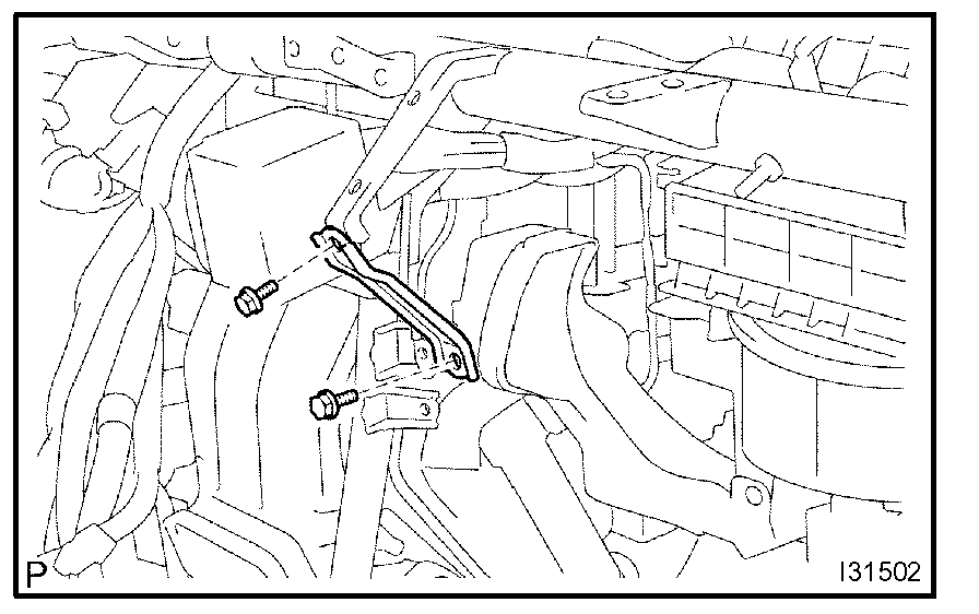
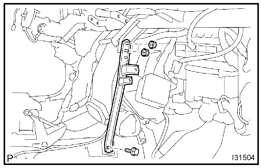
14. REMOVE INSTRUMENT PANEL BRACE SUB-ASSEMBLY NO.2
a. Remove the clamp, nut and passenger side junction block.
b. Remove the bolt and earth wire.
c. Remove the nut and clamp.
d. Remove the 2 nuts, bolt and instrument panel brace sub-assembly No.2.
15. REMOVE HEATER TO FOOT DUCT NO.3
a. Remove the clip and heater to foot duct No.3.
16. REMOVE HEATER TO FOOT DUCT NO.1
a. Remove the clip and heater to foot duct No.1.
17. DISCONNECT STEERING COLUMN ASSEMBLY
a. Remove the 3 nuts and driver side junction block.
b. Remove the 2 nuts and steering side connector block.
c. Release the 2 clamps.
d. Remove the 3 bolts, disconnect the steering column assembly.
18. REMOVE INSTRUMENT PANEL REINFORCEMENT
a. Disconnect the 7 clamps and the wire harness.
b. Remove the 3 nuts, disconnect the 3 earth wires
c. Remove the 3 caps, 7 bolts and instrument panel reinforcement.
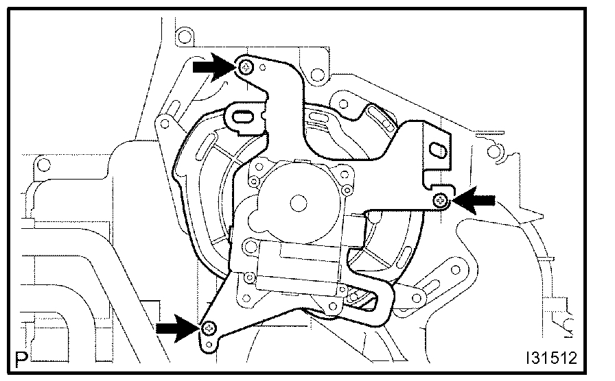
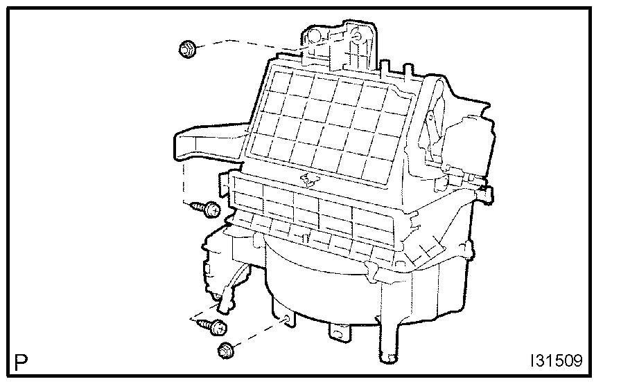
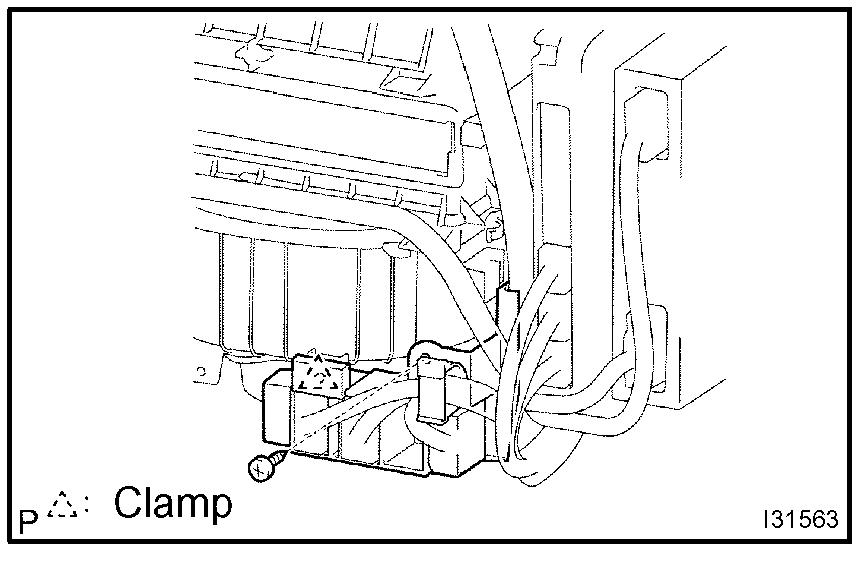
19. REMOVE BLOWER ASSEMBLY
a. Disconnect the connectors.
b. Remove the screw, clamp and blower connector holder.
c. Disconnect the 6 clamps and the wire harness.
d. Remove the 2 screws, 2 nuts and blower assembly.
20. REMOVE DEFROSTER NOZZLE ASSEMBLY LOWER
a. Release the 4 fitting claws, remove the defroster nozzle assembly lower.
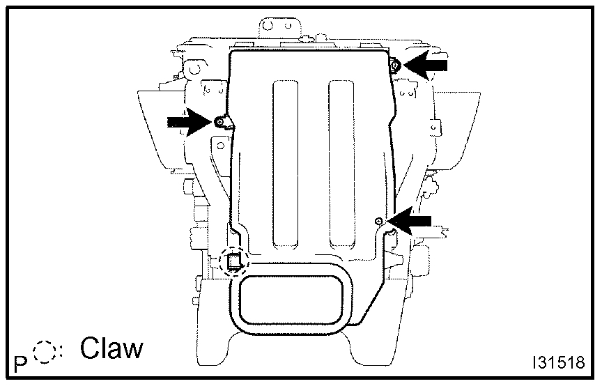
21. REMOVE AIR CONDITIONING RADIATOR ASSEMBLY
a. Disconnect the connectors.
b. Remove the 2 nuts and air conditioning radiator assembly.
22. REMOVE MODE DAMPER SERVO SUB-ASSEMBLY
a. Remove the 3 screws and mode damper servo sub-assembly.
23. REMOVE HEATER RADIATOR UNIT SUB-ASSEMBLY
a. Release the 2 fitting claws, remove the piping clamp.
b. Remove the heater radiator unit sub-assembly.
NOTE: Prepare a support plate and waste to catch the leaked coolant.
24. REMOVE AIRMIX DAMPER SERVO SUB-ASSEMBLY
a. Remove the 3 screws and air mix damper servo sub-assembly.
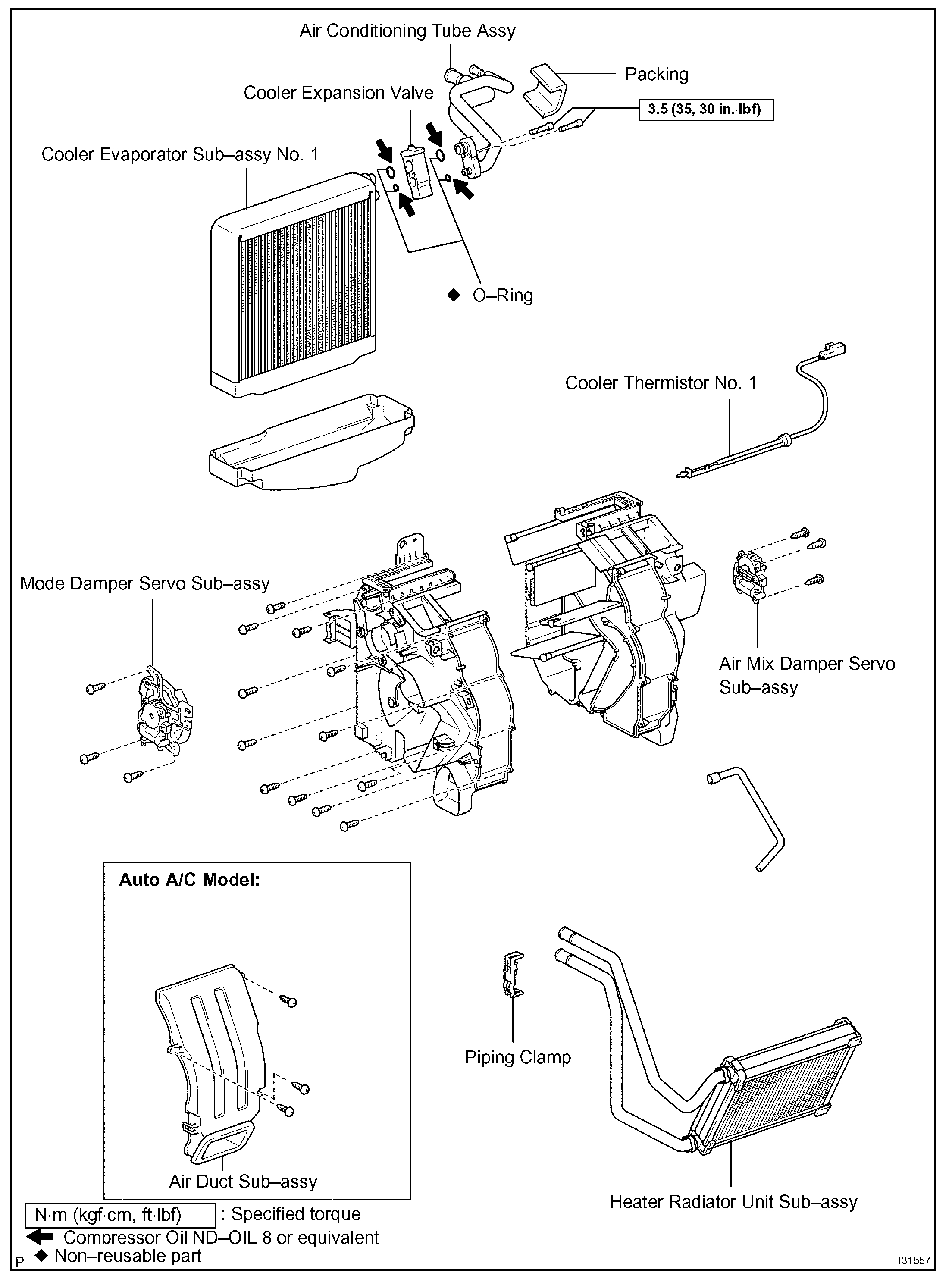
25. REMOVE AIR CONDITIONING TUBE ASSEMBLY
a. Remove the packing.
b. Using a hexagon wrench 4 mm (0.16 in.), remove the 2 hexagon bolts and air conditioning tube assembly.
c. Remove the 2 O-rings from the air conditioning tube assembly.
26. REMOVE COOLER EXPANSION VALVE
a. Remove the cooler expansion valve from the cooler evaporator sub-assembly No.1.
27. REMOVE COOLER THERMISTOR NO.1
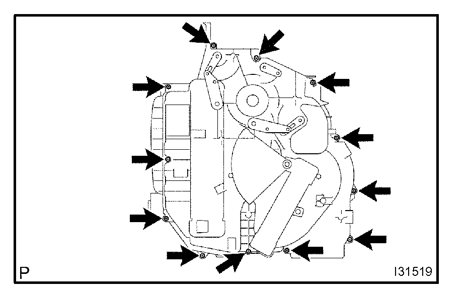
28. REMOVE COOLER EVAPORATOR SUB-ASSEMBLY NO.1
a. Auto A/C model:
Release the fitting claw, remove the 3 screws and air duct sub-assembly.
b. Remove the 12 screws and heater case LH.
c. Remove the cooler evaporator sub-assembly No.1 from the heater case RH.
d. Remove the 2 O-rings from the cooler evaporator sub-assembly No.1.
29. INSTALL COOLER EVAPORATOR SUB-ASSEMBLY NO.1
a. Apply compressor oil to the contact surfaces of 2 new O-rings and the cooler expansion valve and install them.
Compressor oil: ND-OIL 8 or equivalent
b. Install the cooler evaporator sub-assembly No.1 to the heater case RH
c. Install the heater case LH with the 12 screws.
d. Auto A/C model:
Install the air duct sub-assembly with the 3 screws.
30. INSTALL COOLER EXPANSION VALVE
a. Install the cooler expansion valve to the cooler evaporator No.1.
31. INSTALL AIR CONDITIONING TUBE ASSEMBLY
a. Apply compressor oil to the contact surfaces of 2 new O-rings and the air conditioning tube assembly and install them.
Compressor oil: ND-OIL 8 or equivalent
b. Using a hexagon wrench 4 mm (0.16 in.), install the air conditioner tube assembly and 2 hexagon bolts to the cooler evaporator sub-assembly No.1.
Torque: 3.5 N.m (35 kgf.cm, 30 in.lbf)
c. Install the packing.
HINT: Securely attach so that the gap in the packing will not be mode.
32. INSTALL AIR CONDITIONING RADIATOR ASSEMBLY
a. Install the air conditioning radiator assembly with the 2 nuts.
Torque: 1.5 N.m (15 kgf.cm, 12 in.lbf)
b. Connect the connector.
33. INSTALL DEFROSTER NOZZLE ASSEMBLY LOWER
a. Install the defroster nozzle assembly lower.
NOTE: After locating the pin (1) in the illustration, install (2), then (3).
34. INSTALL BLOWER ASSEMBLY
a. Install the blower assembly with the 2 screws and 2 nuts.
Torque: 1.5 N.m (15 kgf.cm, 12 in.lbf)
b. Install the 6 clamps, connect the wire harness.
c. Install the blower connector holder with the screw and clamp.
d. Connect the connectors.
35. INSTALL INSTRUMENT PANEL REINFORCEMENT
a. Install the instrument panel reinforcement with the 7 bolts and 3 caps.
b. Install the 3 earth wires with the 3 nuts.
c. Install the 7 clamps, connect the wire harness.
36. INSTALL STEERING COLUMN ASSEMBLY
a. Install the steering column assembly with the 3 bolts.
b. Install the 2 clamps.
c. Install the steering side connector block with the 2 nuts.
Torque: 8.4 N.m (85 kgf.cm, 73 in.lbf)
d. Install the driver side junction block with the 3 nuts.
Torque: 8.4 N.m (85 kgf.cm, 73 in.lbf)
37. INSTALL INSTRUMENT PANEL BRACE SUB-ASSEMBLY NO.2
a. Install the instrument panel brace sub-assembly No.2 with the 2 nuts and bolt.
b. Install the nut and clamp.
c. Install the earth wire with the bolt.
d. Install the passenger side junction block with the nut and clamp.
Torque: 8.4 N.m (85 kgf.cm, 73 in.lbf)
38. INSTALL INSTRUMENT FINISH PANEL RETAINER LOWER
a. Install the instrument finish panel retainer lower with the 2 bolts.
39. INSTALL INSTRUMENT PANEL BRACE SUB-ASSEMBLY NO.1
a. Install the instrument panel brace sub-assembly No.1 with the nut.
b. Install the bolt and screw.
Torque: 9.8 N.m (100 kgf.cm, 87 in.lbf) (Screw)
c. Install the 2 clamps.
d. Install the 2 earth wires with the 2 bolts.
40. INSTALL INSTRUMENT PANEL SAFETY PAD SUB-ASSEMBLY
41. INSTALL COOLER REFRIGERANT SUCTION HOSE NO.1
a. Lubricate new O-ring with compressor oil and install them to the hose.
Compressor oil: ND-OIL 8 or equivalent
b. Install the cooler refrigerant suction hose No.1 and piping clamp.
HINT: After connection, check the fitting for claw of the piping clamp.
42. INSTALL COOLER REFRIGERANT LIQUID PIPE A
HINT: Install in the same way as the cooler refrigerant suction hose No.1.
43. ADD COOLANT
44. CHARGE REFRIGERANT
SST 07110-58060 (07117-58060, 07117-58070, 07117-58080, 07117-58090, 07117-78050, 07117-88060, 07117-88070, 07117-88080)
Specified amount: 550 ± 50 g (19.37 ± 1.76 oz.)
45. WARM UP ENGINE
46. CHECK FOR ENGINE COOLANT LEAKS
47. INSPECT LEAKAGE OF REFRIGERANT
_______________________________________________________________________________________
The directions are for all aspects of the possible issues I mentioned. Feel free to let me know if you have questions.
Take care,
Joe
Images (Click to make bigger)
SPONSORED LINKS
Thursday, November 26th, 2020 AT 9:53 AM