Hello,
Please see diagrams below for starter wiring layout.
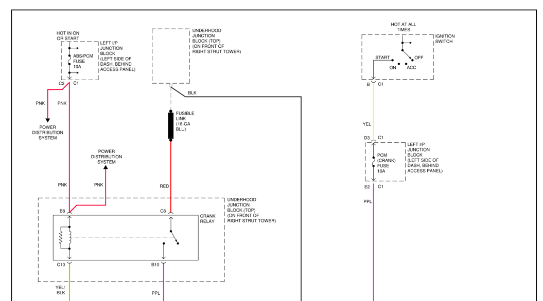
The crank request comes from the ignition switch, pin B, yellow wire.
The voltage is then transferred via the PCM crank fuse(10A) in left instrument panel junction block.
From there via purple wire to the PCM pin 23, connector C2.
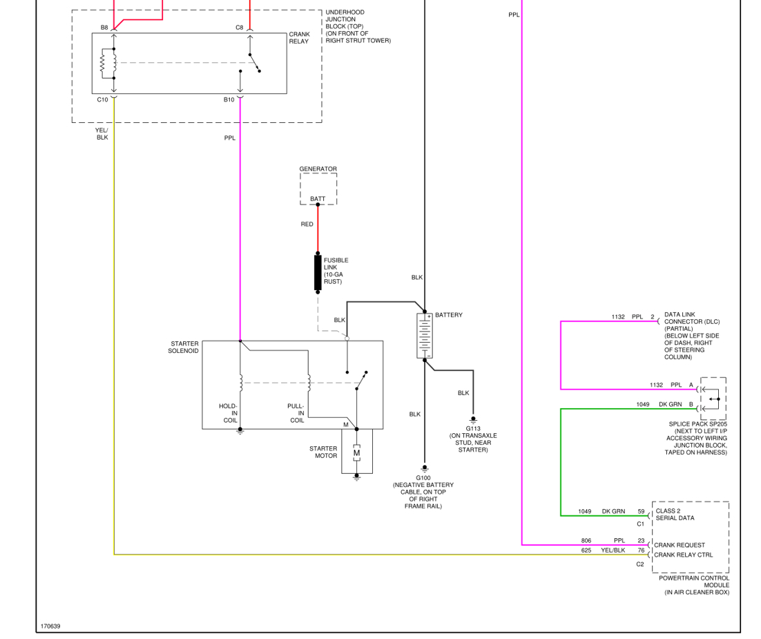
The PCM then outputs a switched ground at pin 76, connector C2, yellow/black wire to terminal C10 at the crank relay in the under-hood junction block.
This then switches the crank relay on to transmit 12V via terminal B10 out on purple wire to the starter solenoid.
The crank relay is supplied with ignition 12V at terminal B8 from ABS/PCM fuse (10A) in left instrument panel junction block and with constant 12V at terminal C8.
You can check 12V or ground by using a test light or voltmeter.
How to use:
https://www.2carpros.com/articles/how-to-use-a-test-light-circuit-tester
and
https://www.2carpros.com/articles/how-to-use-a-voltmeter
How to test relay:
https://www.2carpros.com/articles/how-to-check-an-electrical-relay-and-wiring-control-circuit
How starter works:
https://www.2carpros.com/articles/how-a-starter-and-solenoid-works
Hope this helps.
Cheers, Boris
Images (Click to make bigger)
SPONSORED LINKS
Friday, January 26th, 2024 AT 7:27 AM