Welcome to 2CarPros.
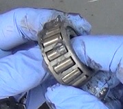
I'm not familiar with any issues with the race. What were you told?
First, here is an excellent link that you will find helpful when doing this repair. The directions specific to your vehicle will follow.
https://www.2carpros.com/articles/bearing-press-how-to-use
Well to remove and replace the bearing, the steering knuckle needs removed. As far as the press, it will work fine for this.
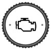
Here are the directions for removal of the steering knuckle. The attached pictures correlate with the directions.
++++++++++++++++++++++++++++++++++++++++++++++++++++++++++++++++++++
11-16
REMOVAL AND INSTALLATION
pic 1
REMOVAL
1. Remove front wheel.
Torque: 103 Nm (76 ft. lbs.)
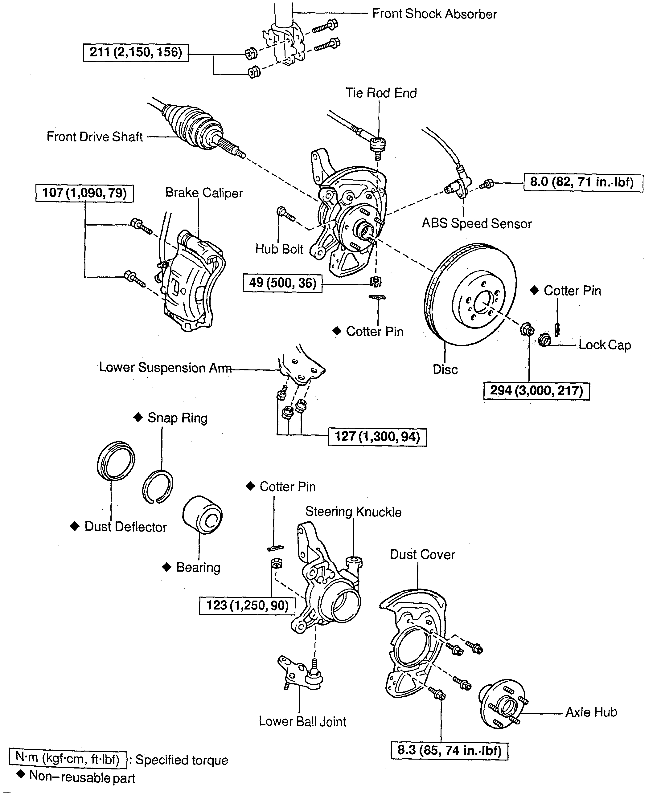
2. Check bearing backlash and axle hub deviation.
a. Remove the 2 bolts, brake caliper and disc.
b. Support the brake caliper securely.
pic 2
c. Using a dial indicator near the center of the axle hub and check the backlash in the bearing shaft direction.
Maximum: 0.05 mm (0.0020 inch).
If the backlash exceeds the maximum, replace the bearing.
d. Using a dial indicator, check the deviation at the surface of the axle hub outside the hub bolt.
Maximum: 0.05 mm (0.0020 inch).
If the deviation exceeds the maximum, replace the bearing.
e. Install the disc, 2 bolts and brake caliper.
Torque: 107 Nm (79 ft. lbs.)
pic 3
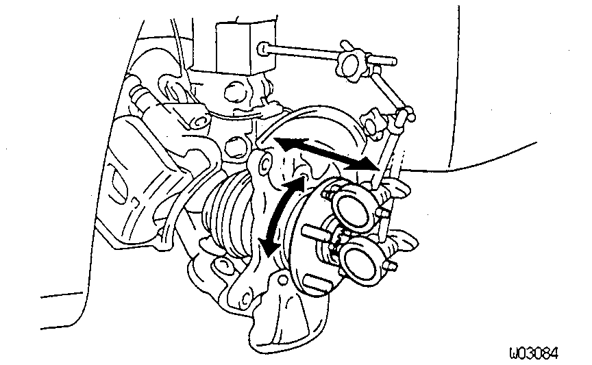
3. Remove drive shaft lock nut.
a. Remove the cotter pin and lock cap.
b. With applying the brakes, remove the nut.
Torque: 294 Nm (217 ft. lbs.)
c. Remove the brake caliper and disc.
4. Remove ABS speed sensor and wire harness clamp.
Torque: 8.0 Nm (71 inch lbs.)
pic 4
5. Loosen 2 nuts on lower side of shock absorber.
Torque: 211 Nm (156 ft. lbs.)
HINT: Do not remove the bolts.
HINT: At the time of installation, coat the nut's thread with engine oil.
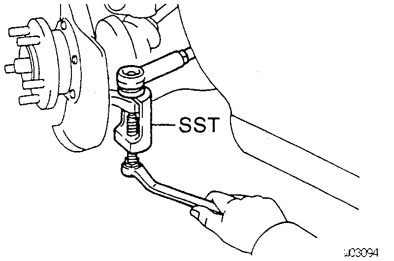
6. Disconnect tie rod end from steering knuckle.
a. Remove the cotter pin and nut.
Torque: 49 Nm (36 ft. lbs.)
pic 5
b. Using Special Service Tool (SST) 09610 - 20012, disconnect the tie rod end from the steering knuckle.
pic 6
7. Disconnect lower ball joint from lower arm. Remove the 2 nuts and bolt.
Torque: 127 Nm (94 ft. lbs.)
8. Remove steering knuckle with axle hub.
a. Remove the 2 bolts on the lower side of the shock absorber.
b. Remove the steering knuckle with the axle hub.
CAUTION: Be careful not to damage the oil seal with drive shaft.
9. Install in reverse order of removal.
10. After installation, check the ABS speed sensor signal and front wheel alignment.
INSTALLATION
Installation is in the reverse order of removal. After installation, check ABS speed signal and front wheel alignment.
++++++++++++++++++++++++++++++++++++++++++++++++++++++++++++++++++++
3-10
Here are the directions for removal and replacement of the bearing once the knuckle has been removed.
DISASSEMBLY AND ASSEMBLY
pic 7
DISASSEMBLY
1. Remove dust deflector, using a screwdriver.
pic 8
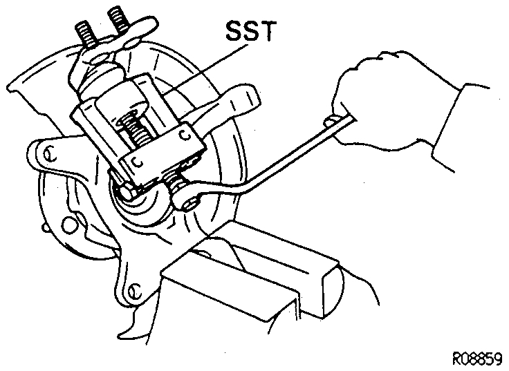
2. Remove lower ball joint.
a. Remove the cotter pin and nut.
b. Using Special Service Tool (SST) 09628 - 62011, remove the lower ball joint.
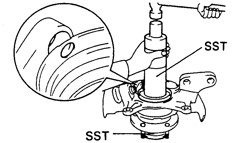
3. Remove axle hub.
pic 9
a. Using SST 09520 - 00031, remove the axle hub.
pic 10
b. Using SST 09950 - 00020, 09950 - 60010 (09951 - 00400), 09950 - 70010 (09951 - 07100) and a press, remove the inner race (outside) from the axle hub.
4. Remove dust cover. Using a torx wrench (T30), remove the 4 bolts and dust cover.
pic 11
5. Remove bearing from steering knuckle.
a. Using snap ring pliers, remove the snap ring.
b. Place the inner race on the outside of the bearing.
c. Using SST 09310 - 35010, 09527 - 17011 and a press, remove the bearing.
ASSEMBLY
pic 12
1. Install bearing.
a. Using SST 09608 - 32010 and a press, install a new bearing to the steering knuckle.
b. Using snap ring pliers, install a new snap ring.
2. Install dust cover.
Using a torx wrench (T30),torque the 4 bolts.
Torque: 8.3 Nm (74 inch lbs.).
pic 13
3. Install front axle hub, using SST 09310 - 35010, 09608 - 32010 and a press.
4. Install lower ball joint.
a. Install the lower ball joint and torque the nut.
Torque: 123 Nm (90 ft. lbs.).
b. Install a new cotter pin.
pic 14
5. Install dust deflector; using SST 09316 - 60011 (09316 - 00011, 09316 - 00041), 09608-32010 and a hammer.
HINT: Align the holes for the ABS speed sensor in the dust deflector and steering knuckle.
______________________________________________
Due to the extreme conditions you mentioned, I strongly recommend checking tie rods, ball joints, and anything related to the steering. This would be the time for replacement if you find they are bad.
Let me know if this helps or if you have other questions.
Take care,
Joe
Images (Click to make bigger)
SPONSORED LINKS
Monday, June 24th, 2019 AT 7:40 PM