Good morning,
This looks to be an electrical issue with the sensor controls. I attached the flow chart for you to follow along with a wiring diagram. Make sure the fuse is good and there is the power to the heater portion of the sensor.
https://www.2carpros.com/articles/how-to-check-wiring
https://www.2carpros.com/articles/how-to-check-wiring
https://www.2carpros.com/articles/how-to-check-a-car-fuse
Let me know the results.
https://www.2carpros.com/articles/how-to-test-an-oxygen-sensor-02-sensor
Roy
CIRCUIT DESCRIPTION
Heated Oxygen Sensors (HO2S) are used in order to minimize the time that is required for closed loop fuel control operation and to allow accurate catalyst monitoring. The oxygen sensor heater greatly decreases the amount of time required for fuel control sensor HO2S 1 to become active. The oxygen sensor heater is required by the catalyst monitor sensor HO2S 2 in order to maintain a sufficiently high temperature. This allows accurate exhaust oxygen content readings further from the engine.
The Powertrain Control Module (PCM) will run the heater test only after a cold start, determined by the engine coolant temperature and the intake air temperature at the time of startup, and only once during an ignition cycle. When the engine is started the PCM will monitor the HO2S voltage. When the HO2S voltage indicates a sufficiently active sensor, the PCM determines how much time has elapsed since startup. If the PCM determines that too much time was required for HO2S 1 to become active, DTC P0135 will set. The time it should take the HO2S to reach operating temperature is based on the engine coolant temperature at startup and the average mass air flow since startup. Higher average airflow or higher startup engine coolant temperature means shorter time to HO2S activity.
CONDITIONS FOR RUNNING THE DTC
There are no active TP, MAP, MAF, ECT, IAT, fuel injector circuit, EVAP, or AIR DTCs present.
The Intake Air Temperature (IAT) is less than 35°C (95°F) at startup.
The Engine Coolant Temperature (ECT) is less than 35°C (95°F) at startup.
The IAT and the ECT are within 6°C (42°F) of each other at startup.
The system voltage is at least 9.0 volts and less than 18.0 volts.
The AIR pump is commanded OFF.
CONDITIONS FOR SETTING THE DTC
HO2S 1 voltage remains within 150 mV of the bias voltage, or approximately 450 mV, for more time than it should. The amount of time varies depending on the engine coolant temperature at startup and the average air flow since startup, but will not exceed 2.5 minutes.
ACTION TAKEN WHEN THE DTC SETS
The PCM will illuminate the Malfunction Indicator Lamp (MIL) during the second consecutive trip in which the diagnostic has been run and failed.
If equipped with traction control, the PCM will command the Electronic Brake And Traction Control Module (EBTCM) via the serial data circuit to turn OFF traction control, and the EBTCM will illuminate the TRACTION OFF lamp.
The PCM will store conditions which were present when the DTC set as Freeze Frame and Failure Records data.
CONDITIONS FOR CLEARING THE MIL/DTC
The PCM will turn OFF the MIL during the third consecutive trip in which the diagnostic has been run and passed.
The History DTC will clear after 40 consecutive warm-up cycles have occurred without a malfunction.
The DTC can be cleared by using a scan tool.
DIAGNOSTIC AIDS
Inspect for:
IMPORTANT: Remove any debris from the connector surfaces before servicing a component. Inspect the connector gaskets when diagnosing or replacing a component. Ensure that the gaskets are installed correctly. The gaskets prevent contaminate intrusion.
Poor terminal connection - Inspect the harness connectors for backed out terminals, improper mating, broken locks, improperly formed or damaged terminals, and faulty terminal to wire connection. Use a corresponding mating terminal to test for proper tension.
Damaged harness - Inspect the wiring harness for damage. If the harness inspection does not reveal a problem, observe the display on the scan tool while moving connectors and wiring harnesses related to the sensor. A change in the scan tool display may indicate the location of the fault.
PCM and engine grounds for clean and secure connections
If the DTC is determined to be intermittent, reviewing the Failure Records can be useful in determining when the DTC was last set.
TEST DESCRIPTION
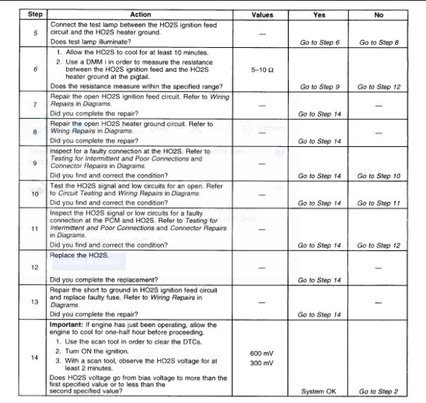
The numbers below refer to the step numbers on the diagnostic table.
2. The HO2S should be allowed to cool before performing this test. If the HO2S heater is functioning, the signal voltage will gradually increase or decrease as the sensor element warms. If the heater is not functioning, the HO2S signal will remain near the 450-mv bias voltage.
4. This step ensures that the ignition feed circuit to the HO2S is not open or shorted. The test lamp should be connected to a good ground, in case the HO2S low or HO2S heater ground circuit is faulty.
5. This step tests the HO2S heater ground circuit.
6. This step inspects for an open or shorted HO2S heater element. The heater element resistance will vary according to HO2S temperature. A hot HO2S heater element will measure much more resistance than a HO2S heater element that is at ambient temperature. It is important to allow the HO2S to cool before measuring the HO2S heater element resistance.
Images (Click to make bigger)
SPONSORED LINKS
Sunday, March 28th, 2021 AT 5:01 AM