Hello and welcome to 2CarPros. It looks like you have done a bit of work for your concern but I do not see that you replaced the coolant cap or the thermostat? Here is the information on how the cooling system works. No, I do not see the transmission sensor having an issue with it overheating, but a shift issue yes. Here is the information on the cooling system:
Collision
� 12
2005 Chevy Truck Venture FWD
�
V6-3.4L VIN E
�
�
Cooling System Description
Vehicle� Engine, Cooling and Exhaust� Cooling System� Description and Operation� Components� Cooling System Description
COOLING SYSTEM DESCRIPTION
Cooling System� Description and Operation
Cooling Fan Control
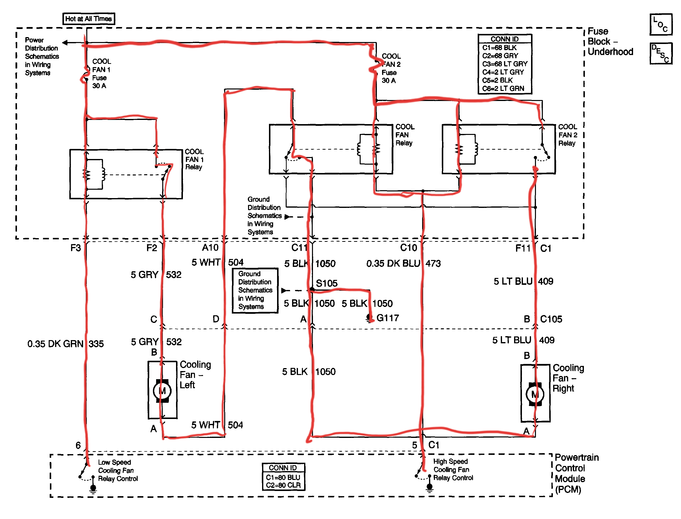
� The� engine cooling fan� system consists of electrical� cooling fans and 3� fan relays. The relays are arranged in a series/parallel configuration that allow the Powertrain Control Module� (PCM)� to operate both fans together at low or high speeds. The cooling fans and fan relays receive battery positive voltage from the underhood junction block. The ground path is provided at G117.
� During low speed operation, the PCM supplies the ground path for the low speed fan relay through the� low speed cooling fan relay� control circuit. It energizes the cooling fan 1 relay coil, closes the relay contacts, and supplies battery positive voltage from the cool fan 1 maxifuse- through the� cooling fan motor� supply voltage circuit to the left cooling fan. The ground path for the left cooling fan is through the� cooling fan relay� and the right cooling fan. The result is a series circuit with both fans running at low speed.
� During high speed operation the PCM supplies the ground path for the cooling fan 1 relay through the low speed cooling fan relay control circuit After a 3-second delay, the PCM supplies a ground pattern for the cooling fan 2 relay and the cooling fan relay through the� high speed cooling fan relay� control circuit. This energizes the cooling fan relay coil, closes the relay contacts, and provides a ground path for the left cooling fan. At the same time the cooling fan 2 relay coil is energized closing the relay contacts and provides battery positive voltage from the cool fan 2 maxifuse on the cooling fan motor supply voltage circuit to the right cooling fan During high speed fan operation, both engine cooling fans have there own ground path. The result is a parallel circuit with both fans running at high speed.
Engine Coolant Indicators Hot Coolant Temp
� The IPC illuminates the hot coolant temperature indicator in the message center when the IPC determines that the coolant temperature is greater than� 128°C (262°F). The IPC receives a class 2 message from the PCM indicating the coolant temperature.
Coolant Level Control
� The engine cooling system contains an engine coolant level module which alerts the driver in the event of a coolant loss. The coolant level module sends out a coolant loss signal over the low coolant level indicator control circuit via the underhood accessory wiring junction block. If the coolant level module reads a low coolant level in the cooling system, the switch closes. The instrument cluster has a coolant level warning indicator that receives power from the fuse block ignition 1 voltage. Ground is provided by the ground circuits via the underhood accessory wiring junction block to G1 13.
Coolant Heater
� The optional engine coolant heater (RPO K05) is rated at 400 watts and supplies 1365 btu/hr. The engine coolant heater operates using 110-volt AC external power and warms the coolant in the� engine block� area for improved starting in very cold weather, up to� -29°C (-20°F). The coolant heater helps reduce fuel consumption when a cold engine is warming up. The unit is equipped with a detachable AC power cord. A weather shield on the cord protects the plug when not in use.
Cooling System
� The cooling system maintains an efficient engine operating temperature during all engine speeds and operating conditions. The cooling system removes approximately one-third of the heat produced by the burning of the air-fuel mixture. When the engine is cold, the system cools slowly or not at all. This allows the engine to warm quickly.
Cooling Cycle
� Coolant is drawn from the� radiator� outlet and into the� water pump� inlet by the water pump. Some coolant will be pumped from the water pump to the� heater core, then back to the water pump. This provides the passenger compartment with heat and defrost.
� Coolant is also pumped through the water pump outlet and into the engine block. In the engine block, the coolant circulates through the water jackets surrounding the cylinders where the coolant absorbs heat.
� The coolant is then forced through the� cylinder head gasket� openings and into the� cylinder heads. In the cylinder heads, the coolant flows through the water jackets surrounding the combustion chambers and valve seats, where the coolant absorbs additional heat.
� Coolant is also directed to the throttle body. There it circulates through passages in the casting. During initial start up, the coolant assists in warming the throttle body. During normal operating temperatures, the coolant assists in keeping the throttle body cool.
� From the cylinder heads, the coolant is then forced to the� thermostat. The coolant will either be stopped at the thermostat until the engine is warmed, or the coolant will flow through the thermostat and into the radiator where the coolant is cooled and the coolant cycle is completed.
� Operation of the cooling system requires proper functioning of all cooling system components. The cooling system consists of the following components:
Coolant
� The engine coolant is a solution made up of a 50-50 mixture of DEX-COOL and clean drinkable water. The coolant solution carries excess heat away from the engine to the radiator, where the heat is dissipated to the atmosphere.
Radiator
� The radiator is a� heat exchanger. It consists of a core and two tanks. The aluminum core is a crossflow tube and fin design. This is a series of tubes that extend side to side from the inlet tank to the outlet tank. Fins are placed around the outside of the tubes to improve heat transfer from the coolant to the atmosphere. The inlet and outlet tanks are molded with a high-temperature, nylon-reinforced plastic. A high-temperature rubber gasket seals the edge of the tank flange. The tanks are clamped to the core with clinch tabs. The tabs are part of the aluminum header at each end of the core. The radiator also has a drain cock which is located in the bottom of the left hand tank. The drain cock includes the drain cock seal.
� The radiator removes heat from the coolant. The fins on the core absorb heat from the coolant passing through the tubes. As air passes between the fins, air absorbs heat and cools the coolant.
� During vehicle use, the coolant heats and expands. The coolant that is displaced by this expansion flows into the� surge tank. As the coolant circulates, air is allowed to exit. This is an advantage to the cooling system. Coolant without bubbles absorbs heat much better than coolant with bubbles.
Pressure Cap
� The pressure cap is a cap that seals and pressurizes the cooling system. It contains a blow off or pressure valve and a vacuum or atmospheric valve. The pressure valve is held against its seat by a spring of predetermined strength, which protects the radiator by relieving pressure that exceeds 15 psi. The vacuum valve is held against the seat by a spring. The spring permits opening of the valve in order to relieve the vacuum which is created as the cooling system cools off. The vacuum, if not relieved, might cause the radiator to collapse.
� The pressure cap allows pressure in the cooling system to build up. As the pressure builds, the boiling point of the coolant also increases. Therefore, the coolant can be safely run at a temperature much higher than the boiling point of the coolant at atmospheric pressure. The hotter the coolant, the faster the heat moves from the radiator to the cooler. The pressure in the cooling system can get too high, however. When the pressure exceeds the strength of the spring, the pressure valve rises so that the excess pressure can escape. As the engine cools, the temperature of the coolant drops and a vacuum is created in the cooling system. This vacuum causes the vacuum valve to open, allowing outside air into the cooling system. This equalizes the pressure in the cooling system with atmospheric pressure, preventing the radiator from collapsing.
Coolant Recovery System
� The coolant recovery system consists of a plastic� coolant recovery reservoir� and overflow tube. The recovery reservoir is also called a recovery tank or� expansion tank. This tank is partially filled with coolant and is connected to the radiator fill neck by the overflow tube. Coolant can flow back and forth between the radiator and the reservoir.
� A cooling system with a coolant recovery reservoir is a closed system. When the pressure in the cooling system gets too high, the pressure will open the valve in the pressure cap. This allows the expanded coolant to flow through the overflow tube and into the recovery reservoir. As the engine cools, the temperature of the coolant drops and a vacuum is created in the cooling system. This vacuum opens the vacuum valve in the pressure cap, allowing some of the coolant in the reservoir to be siphoned back into the radiator. Under normal operating conditions, no coolant is lost. Although the coolant level in the recovery reservoir fluctuates, the radiator and cooling system are kept full. A coolant recovery reservoir eliminates almost all air bubbles from the cooling system. Coolant without bubbles absorbs heat much better than coolant with bubbles.
Air Baffles and Seals
� The cooling system uses deflectors, air baffles, and air seals in order to increase system cooling. Deflectors are installed under the vehicle in order to redirect airflow through the radiator which increases cooling. Air baffles are also used in order to direct airflow into the radiator and increase cooling. Air seals prevent air from bypassing the radiator and the A/C condenser. Air seals also prevent recirculation of the air for better hot-weather cooling and A/C condenser performance.
Water Pump
� The water pump is a centrifugal vane impeller type pump. The pump consists of a housing with coolant inlet and outlet passages and an impeller. The impeller is a flat plate mounted on the pump shaft with a series of flat or curved blades or vanes. When the impeller rotates, the coolant between the vanes is thrown outward by centrifugal force. The impeller shaft is supported by one or more sealed bearings.
� These sealed bearings never need to be lubricated. With a sealed bearing, grease cannot leak out. And dirt and water cannot get in.
� The purpose of the water pump is to circulate coolant throughout the cooling system. The water pump is driven by the� crankshaft� via the� drive belt.
Thermostat
� The thermostat is a coolant flow control component. The thermostat regulates the operating temperature of the engine. The thermostat utilizes a temperature sensitive wax-pellet element. The element connects to a valve through a� piston. When the element is heated, the element expands and exerts pressure against a rubber diaphragm. This pressure forces the valve to open. As the element is cooled, it contracts. This contraction allows a spring to push the valve closed.
� When the coolant temperature is below� 91°C (195°F), the thermostat valve remains closed. This prevents circulation of the coolant to the radiator and allows the engine to warm up quickly. After the coolant temperature reaches� 91°C (195°F), the thermostat valve will open. The coolant is then allowed to circulate through the thermostat to the radiator where the engine heat is dissipated to the atmosphere. The thermostat also provides a restriction in the cooling system, even after it has opened. This restriction creates a pressure difference which prevents cavitation at the water pump and forces coolant to circulate through the engine block.
Engine Oil Cooler
� The engine� oil cooler� is a heat exchanger. The cooler is located inside the left side end tank of the radiator. The engine oil temperature is controlled by the temperature of the engine coolant that surrounds the oil cooler in the radiator.
� The engine� oil pump� directs the oil through the engine oil cooler line to the oil cooler. The oil then flows through the cooler where the engine coolant absorbs heat from the oil. The oil is then pumped through the oil cooler return line, to the� oil filter, to the engine block oil system.
Transmission Oil Cooler
� The transmission oil cooler is a heat exchanger. The cooler is located inside the right side end tank of the radiator. The temperature of the transmission fluid is regulated by the engine coolant that surrounds the oil cooler as the transmission fluid passes through the cooler.
� The transmission oil pump directs the fluid through the transmission oil cooler feed-line to the oil cooler. The fluid then flows through the cooler while the engine coolant absorbs heat from the fluid The fluid is then pumped through the transmission oil cooler return line, to the transmission
Image (Click to make bigger)
SPONSORED LINKS
Saturday, September 7th, 2019 AT 11:52 PM