Ongoing bout with 1153,155 99 Lexus ES300

Tiny
BRDSMITH15
  • MEMBER
  • 1999 LEXUS ES
  • 160,000 MILES
B2S1 stuck at.66v will not fluctuate, sensor has been replaced multiple times in short period (Denso) OEM, Checked blk/red blk/wht at ECU both show roughly 12v with key on, does this determine Faulty ECU?
Monday, May 13th, 2013 AT 10:34 PM

7 Replies

Tiny
KHLOW2008
  • MECHANIC
  • 41,815 POSTS
You most probably has an open circuit.

Diagnostic Aids

After confirming DTCs P1133 and/or P1153, use scan tool to access CURRENT
DATA to confirm voltage output of heated oxygen sensors (bank No. 1 and 2 sensor No. 1). ECM controls voltage of AF+ and AF- terminals at ECM to a fixed voltage (3.3 volts at AF+ terminal; 3.0 volts at AF- terminal). It is impossible to confirm A/F sensor output voltage without using a scan tool. OBD-II scan tools will display one fifth A/F sensor output voltage as Lexus scan tool will. Using scan tool, read freeze frame data. Freeze frame records engine conditions when malfunction is detected.

During fuel enrichment, output voltage of A/F sensors maybe less than 0.56 volts (2.8 volts on Lexus scan tool). During fuel cut, output voltage of A/F sensors maybe more than 0.76 volt (3.8 volts on Lexus scan tool). If output voltage of A/F sensor remains at 0.66 volt (3.3 volts on Lexus scan tool) during all conditions, A/F sensor circuit may be open. If output voltage of A/F sensor remains at 0.76 volt (3.8 volts on Lexus scan tool) or more during all conditions, A/F sensor circuit may be shorted. If output voltage of A/F sensor remains at 0.56 volt (2.8 volts on Lexus scan tool) or less during all conditions, A/F sensor circuit may be shorted.
Was this
answer
helpful?
Yes
No
Tuesday, May 14th, 2013 AT 10:18 AM
Tiny
BRDSMITH15
  • MEMBER
  • 14 POSTS
Did you see anywhere the test pertaining to the ECU, I read that test determined fault to be within the ECU, I am getting 3.3V, and 12v at connector to sensor? Just unsure how to determine Sensor is the problem as it has had same problem so many times with Denso installed each time, If it is an Open Circuit why is other sensor working Correctly, aren't they on same circuit?
Was this
answer
helpful?
Yes
No
Tuesday, May 14th, 2013 AT 7:40 PM
Tiny
KHLOW2008
  • MECHANIC
  • 41,815 POSTS
The power supply could be from the same circuit but the return lines are individually from each sensor to the designated point of the ECU. Have you tested them for continuity?

Did you go through what I posted previously pertaiing to monitoring the voltage with a scan tool? Your earlier post stated that the voltage stagnates at.66 v and that is what I got the information from.
Was this
answer
helpful?
Yes
No
Wednesday, May 15th, 2013 AT 5:04 AM
Tiny
BRDSMITH15
  • MEMBER
  • 14 POSTS
Yes Scan tool is where I got readings for.66v steady, B1S1 moves properly, Are you familiar with what the close to 12V reading means at ECU, I've read that it determines ECU is at Fault but not sure, I can't find the diagram to check continuity all the way back. If there were a problem with it not reaching temperature fast enough it would code both banks right?
Was this
answer
helpful?
Yes
No
Wednesday, May 15th, 2013 AT 10:45 AM
Tiny
KHLOW2008
  • MECHANIC
  • 41,815 POSTS
Do the proper diagnostics and see what you come up with.

Diagnosis & Repair

1. If other DTCs are displayed, diagnose and repair those DTCs first and retest
system. If only DTC P1133 and/or P1153 is displayed, go to next step.

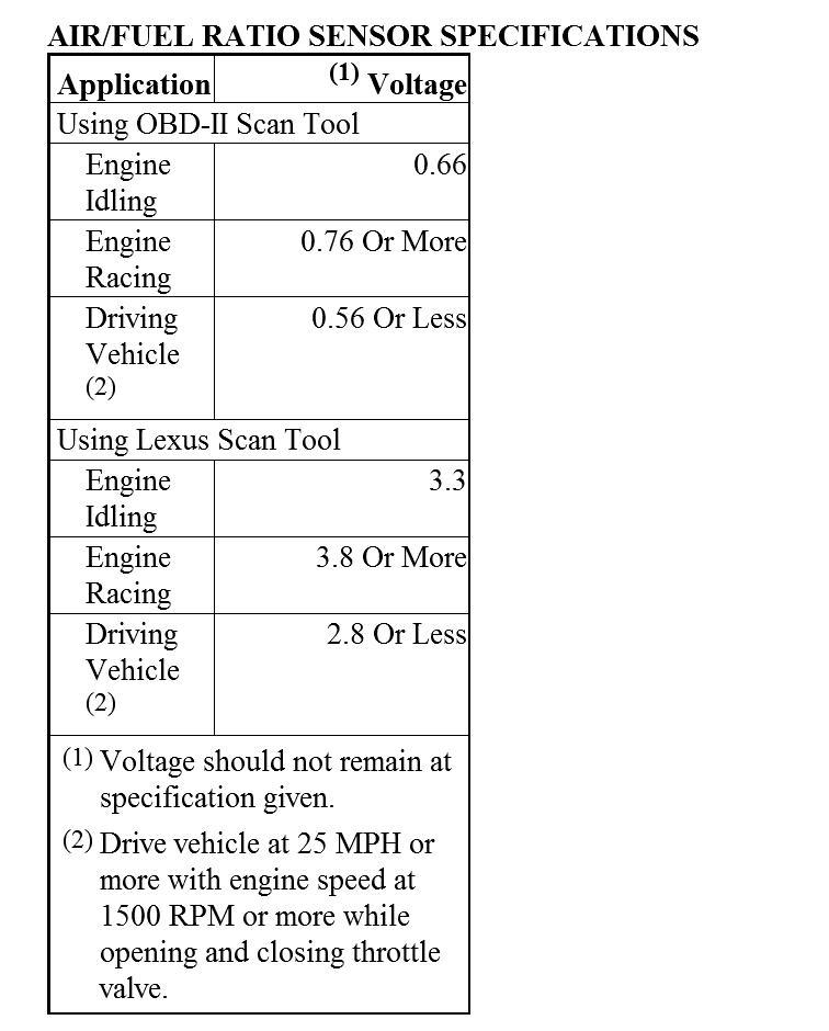
2. Connect scan tool to Data Link Connector (DLC) No. 3. Start engine and raise engine speed to 2500 RPM for approximately 90 seconds. Using scan tool, monitor each A/F sensor output voltage. See AIR/FUEL RATIO SENSOR
SPECIFICATIONS table. If voltage is as specified, go to next step. If voltage is
not as specified, go to step 8.

3. Check for open or short in wiring between ECM and suspect A/F sensor. If problem exists, repair wiring as necessary. If problem does not exist, go to next step.

4. Disconnect suspect A/F sensor harness connector. One A/F sensor is located in each exhaust manifold. Measure resistance between terminal B+ (Black wire) and HT (Back/White wire on bank No. 1 or Black/Red wire on bank No. 2) at A/F sensor connector (component side). Resistance should be.8-1.4 ohms at 68°F (20°C) and 1.8-3.2 ohms at 1472°F (800°C). If resistances are not as specified,
replace appropriate A/F sensor. If resistances are as specified, go to next step.

5. Ensure oil dipstick, oil filler cap, PCV system and all other air induction system components are intact and operating properly. If problem exists, repair as necessary. If problem does not exist, go to next step.

6. Check fuel pressure. If fuel pressure is not within specification, repair as
necessary. If fuel pressure is within specification, go to next step.

7. Check fuel injectors. If problem exists, repair as necessary. If problem does not exist, replace defective A/F sensor.

8. Perform test drive confirmation then go to next step.

9. Clear and recheck for DTCs. If DTCs P1133 and/or P1153 is displayed again,
replace ECM. If DTCs P1133 and P1153 are not displayed again, go to next step.

10. Vehicle either ran out of fuel or problem is intermittent. Check component and ECM connections.
Was this
answer
helpful?
Yes
No
Wednesday, May 15th, 2013 AT 11:10 AM
Tiny
BRDSMITH15
  • MEMBER
  • 14 POSTS
It hasn't ran out of fuel its not intermittent the Sensor WILL NOT move readings, I've already done all this stuff as I've stated other than check fuel pressure b/c it's too hard, and I haven't checked from Connector to ECU b/c Idk what goes where? That's all I'm asking, I did test terminals at ECU and someone said if they both showed 12 volts then ECU was problem is that true or not these are the questions I'm trying to get answered. The sensor is not the problem I'm almost certain, been changed with OEM several times now.
Was this
answer
helpful?
Yes
No
Wednesday, May 15th, 2013 AT 4:50 PM
Tiny
KHLOW2008
  • MECHANIC
  • 41,815 POSTS
I don't know which 2 wires you checked but if it is terminal # 3 and 4 of Connector E10, they should be showing battery voltage. Black/Red is from power supply of circuit opening relay and Black/White is for the heater circuit. Whomever told you this does not know what he is talking about.

I have been trying to show you the proper diagnostic procedures as I see that you are not doing it correctly and you keep insisting that the ECU is bad because someone said so. You don't even know what to test and tells me that you have been through all that I have given you.

Guess I should be spending my time helping someone else.

Good luck.
Was this
answer
helpful?
Yes
No
Thursday, May 16th, 2013 AT 5:56 AM

Please login or register to post a reply.

Sponsored links