No spark?

Tiny
ASEMASTER6371
  • MECHANIC
  • 52,797 POSTS
That comes off the negative side of the coil. With the key on, that should be battery voltage as well. If it does not, it could be a bad coil or the module is grounding the wire.

Roy
Was this
answer
helpful?
Yes
No
Wednesday, July 29th, 2020 AT 11:49 AM (Merged)
Tiny
AARONPSANCHEZ
  • MEMBER
  • 1 POST
  • 1989 FORD RANGER
  • 2.3L
  • 4 CYL
  • 2WD
  • MANUAL
  • 145,000 MILES
Truck cranks just fine, but won't start. Has a new starter in it. There is no spark at the plugs when cranking. If I push it, it starts right up. Drives fine and shifts fine.
Was this
answer
helpful?
Yes
No
Wednesday, July 29th, 2020 AT 11:49 AM (Merged)
Tiny
KASEKENNY
  • MECHANIC
  • 18,907 POSTS
Hi

Your truck has what is called a dual plug inhibit system. What this means is during cranking the ignition module will only fire one set of plugs. Then when it is running it will fire both plugs as normal. The plugs on the right side of the engine are the ones that are to fire during starting so just make sure that you checked those plugs to ensure you truly don't have spark during cranking.

If you don't, I suspect you have an issue with the EEC IV system. Just check the plugs on the right side of the engine and let me know if you don't have spark and we can go further if needed. Otherwise we can go a different direction. Thanks
Was this
answer
helpful?
Yes
No
Wednesday, July 29th, 2020 AT 11:50 AM (Merged)
Tiny
JAYSTUNE
  • MEMBER
  • 6 POSTS
  • 1988 FORD RANGER
  • 6 CYL
  • 4WD
  • MANUAL
  • 110,000 MILES
I am not getting juice to the coil so i'm not getting spark! What sould the reasons be? I turned the key on and tried a test light to the wires to the coil I checked all the fuses please give me help or ideas to check thank you
Was this
answer
helpful?
Yes
No
Wednesday, July 29th, 2020 AT 11:50 AM (Merged)
Tiny
RASMATAZ
  • MECHANIC
  • 75,992 POSTS
I am not getting juice to the coil so i'm not getting spark!

Disconnect a sparkplug wire or 2 and ground it to the engine -have helper crank engine over-do you have a snapping blue spark? If so-you have a fuel related problem, check the fuel pressure to rule out the fuel filter/fuel pump/pressure regulator and listen to the injector/s are they pulsing or hook up a noid light. No snapping blue spark continue to troubleshoot the ignition system-power input to the coil/coil packs, cap and rotor /distributor pick-up coil, ignition control module, ECM, Ignitor cam and crank sensors- Note: If it doesn't apply disregard it
Was this
answer
helpful?
Yes
No
Wednesday, July 29th, 2020 AT 11:50 AM (Merged)
Tiny
GORDO98
  • MEMBER
  • 3 POSTS
  • 1988 FORD RANGER
  • 6 CYL
  • 2WD
  • AUTOMATIC
  • 170,000 MILES
I have a 1988 ford ranger with a 2.9 and I have no spark at all. I got a new coil and checked it to make sure it was good and it has 12volts to it put a new ignition mouduel switched distributers and still no spark I am completley stumped the only thing I can thing of it being is the ecm if that controles spark? Wher could I get the ecm checked at. Is there any thing else to check any info will be great thanks JOSH
Was this
answer
helpful?
Yes
No
Wednesday, July 29th, 2020 AT 11:50 AM (Merged)
Tiny
DAVE H
  • MECHANIC
  • 13,383 POSTS
DISTRIBUTOR OPERATION
A reluctor, containing same number of teeth as engine cylinders, turns with distributor shaft. The pick-up coil contains a permanent magnet, causing a magnetic field around pick-up coil.
As teeth of reluctor approach and pass pick-up coil, the magnetic field builds and collapses. This causes a signal to be sent to the Electronic Control Module (ECM). The ECM turns the ignition coil primary off and on, causing a high voltage surge in the secondary.
Dura-Spark II distributors have both centrifugal and vacuum advance mechanisms. On single diaphragm vacuum units, increased vacuum causes the movable pick-up coil to pivot on lower plate assembly, advancing spark timing.
On dual diaphragm units, outer (primary) diaphragm operates from carburetor vacuum to provide timing advance during normal, off-idle, driving conditions. The inner (secondary) diaphragm operates from intake manifold vacuum and acts to retard ignition timing. The inner diaphragm is connected to outer diaphragm rod by means of sliding linkage. Stronger intake manifold vacuum overrides carburetor vacuum during closed throttle operation to retard timing.
ELECTRONIC CONTROL MODULE OPERATION
Each Dura-Spark II module has 6 wires in 2 connectors. The Red and White wires are ignition feed wires. The White wire is for cranking, and the Red wire provides for normal engine operation. The Red wire circuit contains a 1.1-ohm resistance wire. The current to primary circuit of the ignition coil is turned off and on through Green wire.
The Orange and Purple wires transmit signals to ECM from reluctor (armature) and pick-up coil (stator) in distributor. The Black wire is used to ground ECM through distributor housing.
Electronic control modules of the UIM type, having the third connector, provide for additional spark timing control. This connector receives a signal from the Ignition Barometric Switch, Ignition Timing Vacuum Switch, or the MCU module depending on engine calibration.
IGNITION COIL OPERATION
The ignition coil is energized when ignition switch is in the "ON" or "START" position. The coil contains a positive "BATT" terminal, a negative "TACH" terminal, and a secondary terminal.
A special connector attaches Green wire from ECM to negative coil primary terminal ("TACH"). The wire from ignition switch to positive coil primary terminal ("BATT") is located on opposite side of the connector.
SYSTEM PROTECTION
Dura-Spark systems are protected against electrical currents produced or used by other vehicle component during normal operation. However, damage to ignition system can occur if proper testing procedures are not followed.
Was this
answer
helpful?
Yes
No
Wednesday, July 29th, 2020 AT 11:50 AM (Merged)
Tiny
GORDO98
  • MEMBER
  • 3 POSTS
Thanks for the info. I changed the ecm and still nothing. Please help
Was this
answer
helpful?
Yes
No
+1
Wednesday, July 29th, 2020 AT 11:50 AM (Merged)
Tiny
DAVE H
  • MECHANIC
  • 13,383 POSTS
TESTING
NOTE:All wire colors shown refer to colors of ECM wires. When making tests, wires must be traced back to control module for proper color identification.

SECONDARY WIRE RESISTANCE
Remove distributor cap and disconnect spark plug end of suspected wire(s). Connect ohmmeter leads from terminal inside distributor cap to end of spark plug wire. DO NOT puncture spark plug wire when measuring resistance.
If resistance is below 7000 ohms per foot, spark plug wire is okay. If resistance is over 7000 ohms per foot, replace wire(s). After test, install distributor cap and connect spark plug wire(s).
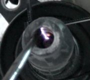
START CIRCUIT
Connect Spark Tester (D81P-6666-A) between ignition coil wire and a good engine ground. Crank engine using vehicle's ignition switch. If no sparks occur at tester gap, proceed to step 2). If sparks occur at tester gap, proceed to RUN CIRCUIT check.
Inspect ignition coil for damage or carbon tracking. Crank engine to verify distributor rotation and proceed to VOLTAGE SUPPLY CIRCUITS test.

Remove ignition coil wire from distributor cap, and install spark tester on wire. Turn ignition switch from "RUN" to "OFF" position. Spark should occur at tester gap each time switch goes from "RUN" to "OFF" position. If no sparks occurred, proceed to CONTROL MODULE VOLTAGE test.
If spark occurs, check distributor cap, adapter, and rotor for damage or wear. Check for roll pin retaining reluctor to sleeve in distributor shaft. Verify Orange and Purple wires are not crossed between distributor and control module.
CONTROL MODULE VOLTAGE
With ignition off, carefully insert straight-pin in Red module wire. DO NOT allow straight-pin to touch ground. Attach negative voltmeter lead to distributor base and positive lead to straight-pin.
Turn ignition switch to the "RUN" position. Measure voltage at the straight-pin in the Red wire. Voltage at pin should read at least 90 percent of battery voltage. If so, proceed to RESISTANCE WIRE test. After reading voltmeter, turn ignition off and remove straight-pin.
If reading was less than 90 percent of battery voltage, check wiring harness between control module and ignition switch. Also check for a worn or damaged ignition switch.
RESISTANCE WIRE
Disconnect control module 2-wire connector and remove coil connector from coil. Connect ohmmeter leads to "BATT" terminal of coil connector and control module harness connector Red wire terminal.
If resistance is.8-1.6 ohms, problem is either intermittent or not in ignition system. If resistance was below.8 ohms or more than 1.6 ohms, replace resistance wire. After test, reconnect all connectors.
VOLTAGE SUPPLY CIRCUITS
Remove spark tester and reconnect coil wire to cap. If starter relay has an "I" terminal, disconnect cable between relay and starter motor at the relay. If starter relay does not have an "I" terminal, disconnect wire to "S" terminal of starter relay. Insert small straight-pins into Red and White control module wires. DO NOT allow straight-pins to contact ground.
Measure voltage at battery. Connect negative voltmeter lead to distributor base. Note voltmeter reading at each of the following circuits. See VOLTAGE SUPPLY CIRCUIT TEST table. Wiggle wiring harness when measuring voltage.
VOLTAGE SUPPLY CIRCUIT TEST
Wire/Termina. LCircuit. Ignition Switch Test Position
Red. Run. Run
White. Start. Start
"BATT"Resistance Wire. Start

Turn ignition off. Reconnect any wires disconnected from starter relay. Remove voltmeter leads, and straight-pins from wiring.
If voltage readings were 90 percent of battery voltage, test results are okay. Proceed to IGNITION COIL VOLTAGE SUPPLY test. If readings were below 90 percent of battery voltage, check for faulty wiring harness connectors or damaged ignition switch.
IGNITION COIL VOLTAGE SUPPLY
Connect negative lead of voltmeter to distributor base and positive lead to "BATT" terminal of ignition coil. Turn ignition switch to "RUN" position and read voltmeter. Turn ignition switch to "OFF" position.
If reading is 6-8 volts, proceed to PICK-UP COIL & DISTRIBUTOR WIRING HARNESS test. If voltage is less than 6 volts or more than 8 volts, proceed to IGNITION COIL PRIMARY RESISTANCE test.
PICK-UP COIL & DISTRIBUTOR WIRING HARNESS
Separate control module 4-wire connector and inspect for corrosion or damage. Connect ohmmeter leads to harness connector terminals that mate with Orange and Purple control module wires. Wiggle wiring harness when measuring resistance.
If resistance is 400-1300 ohms, proceed to CONTROL MODULE-TO-DISTRIBUTOR WIRING HARNESS test. If resistance is less than 400 ohms or more than 1300 ohms, proceed to PICK-UP COIL RESISTANCE test.
CONTROL MODULE-TO-DISTRIBUTOR WIRING HARNESS
Separate 4-wire control module connector. Attach ohmmeter lead to distributor base. Alternately connect the other ohmmeter lead to wiring harness connector terminals that mate with Orange and Purple wires of control module connector.
Resistance should be greater than 70,000 ohms. If within specification, proceed to IGNITION COIL SECONDARY RESISTANCE test. If not, check wiring harness between control module connector and distributor. After test, reconnect 4-wire connector.
IGNITION COIL SECONDARY RESISTANCE
Disconnect and inspect ignition coil connector and coil wire. Connect ohmmeter leads to ignition coil "BATT" terminal and high voltage terminal.
If resistance is 7700-10,500 ohms, coil is okay. Proceed to MODULE-TO-COIL WIRE test. If resistance is below 7700 or greater than 10,500 ohms, replace ignition coil. After test, connect coil wire.
MODULE-TO-COIL WIRE
Disconnect and inspect control module 4-wire connector from coil. Disconnect ignition coil connector from coil. Attach an ohmmeter lead to distributor base and the other to "TACH" terminal of ignition coil connector.
If reading exceeds 100 ohms, replace control module. If reading is 100 ohms or less, inspect wiring harness between control module and ignition coil. After test, connect ignition module and coil connectors.
PICK-UP COIL RESISTANCE
Disconnect distributor connector from wiring harness. Inspect for dirt, corrosion, or damage. Measure resistance across Orange and Purple wires at distributor connector.
If reading is between 400-1000 ohms, pick-up coil is okay. Inspect wiring harness between distributor and control module. If voltage reading is less than 400 ohms or more than 1000 ohms, replace pick-up coil assembly. After test, connect distributor and control module connectors.
IGNITION COIL PRIMARY RESISTANCE
Disconnect ignition coil connector. Connect ohmmeter leads to "BATT" and "TACH" terminals of ignition coil. If resistance is.8-1.6 ohms, coil is okay. Proceed to PRIMARY CIRCUIT CONTINUITY test. If resistance is less than.8 or greater than 1.6 ohms, replace ignition coil. After test, connect ignition coil connector.
PRIMARY CIRCUIT CONTINUITY
Insert a small straight-pin in control module Green wire. DO NOT allow straight-pin to contact ground. Attach voltmeter negative lead to distributor base, and positive lead to pin in Green wire. Measure voltage with ignition switch in "RUN" position.
If reading exceeds 1.5 volts, proceed to GROUND CIRCUIT CONTINUITY test. If reading is 1.5 volts or less, inspect wiring between control module and coil. After test, remove straight-pin.
GROUND CIRCUIT CONTINUITY
Insert a small straight-pin in control module Black wire. DO NOT allow straight-pin to contact ground. Attach voltmeter negative lead to distributor base and positive lead to straight-pin in Black wire. With ignition switch in "RUN" position, measure voltage.
If voltage reading was greater than.5 volt, proceed to DISTRIBUTOR GROUND CIRCUIT CONTINUITY test. If voltage was.5 volt or less, replace control module. After test, remove straight-pin.
DISTRIBUTOR GROUND CIRCUIT CONTINUITY
Separate distributor connector from wiring harness. Inspect for dirt, corrosion, or damage. Connect ohmmeter leads to distributor base and Black wire terminal in distributor connector. Wiggle distributor grommet while measuring resistance.
If resistance is less than one ohm, circuit is okay. If resistance is greater than one ohm, check ground screw in distributor housing. After test, reconnect distributor.
Was this
answer
helpful?
Yes
No
Wednesday, July 29th, 2020 AT 11:50 AM (Merged)
Tiny
GORDO98
  • MEMBER
  • 3 POSTS
Well after several hundred dollars I spent (eec, icm, distributer, and coil plus several hours) I found the problem it was the plug in that went to the coil. Found that and it fired right up
Was this
answer
helpful?
Yes
No
+1
Wednesday, July 29th, 2020 AT 11:50 AM (Merged)
Tiny
JAYSTUNE
  • MEMBER
  • 6 POSTS
  • 1988 FORD RANGER
  • 6 CYL
  • 4WD
  • MANUAL
  • 110,000 MILES
I am not getting any spark the coil is good as I tested it but still no spark from the coil pleases help
Was this
answer
helpful?
Yes
No
Wednesday, July 29th, 2020 AT 11:50 AM (Merged)
Tiny
BLACKOP555
  • MECHANIC
  • 10,371 POSTS
You have to check for a constant +12v at the connector with key on.

On the negative side with engine cranking you hsould be getting a -12v.

You can put a test light in those spots and crank the engine. It should flash. If not one of the two are missing.
Was this
answer
helpful?
Yes
No
Wednesday, July 29th, 2020 AT 11:50 AM (Merged)
Tiny
JONATHAN CHAVEZ
  • MEMBER
  • 1 POST
  • 1987 FORD RANGER
  • 4 CYL
  • 2WD
  • MANUAL
  • 20,000 MILES
Changed module coil pick up coil distributor cap and rotor. No spark.
Was this
answer
helpful?
Yes
No
Wednesday, July 29th, 2020 AT 11:50 AM (Merged)
Tiny
ASEMASTER6371
  • MECHANIC
  • 52,797 POSTS
Good morning,

Did you check for power to the positive side of the coil? You need battery voltage there. If you do, use a test light on the negative side and make sure you have power.

Crank the engine and see if the light flashes while cranking.

Roy
Was this
answer
helpful?
Yes
No
Wednesday, July 29th, 2020 AT 11:50 AM (Merged)
Tiny
BILL51501
  • MEMBER
  • 1 POST
  • 1987 FORD RANGER
  • 147,000 MILES
New coil, dist cap and rotor, plugs & wires
cranks over ok, just no spark.
Every once in a while it sparks 1 time, then no spark
then 1 spark, no spark
Was this
answer
helpful?
Yes
No
Wednesday, July 29th, 2020 AT 11:50 AM (Merged)
Tiny
RIVERMIKERAT
  • MECHANIC
  • 6,110 POSTS
Check ballast resistor. Make sure coil is receiving power. Using a test light, verify the coil is receiving the interrupt signal. Hook clip to ground and probe the negative coil terminal. Make sure distributor stator is properly installed and gapped. And not loose.
Was this
answer
helpful?
Yes
No
Wednesday, July 29th, 2020 AT 11:50 AM (Merged)
Tiny
MIKE LUCKEY
  • MEMBER
  • 38 POSTS
  • 1986 FORD RANGER
  • 2.3L
  • 4 CYL
  • 4WD
  • MANUAL
86 ford ranger, died while driving. Replaced the fuel pump and relay. Then later realized that the pump had no power to it. Also discovered a no spark situation. So, no spark, and no power to the fuel pump. ICM and coil test ok. Put in a new ignition switch. Removed EEC computer, to go to pullnsave to find another. Out of desperation, I tried without the computer installed. LOTS of spark, but still no power to the fuel pump. Weird. Couldn't find a used EEC, buy suspect this may be the problem. Any Ideas? BTW. Also checked the inertia switch. Everything ok there too. Help!
Was this
answer
helpful?
Yes
No
Wednesday, July 29th, 2020 AT 11:50 AM (Merged)
Tiny
HMAC300
  • MECHANIC
  • 48,601 POSTS
There is a fusible link running probably off the starter relay it is a yellow wire leading to fp relay the fusible link is blue and are available at auto parts. Make sure to put correct one in.
Was this
answer
helpful?
Yes
No
+1
Wednesday, July 29th, 2020 AT 11:50 AM (Merged)
Tiny
MIKE LUCKEY
  • MEMBER
  • 38 POSTS
I will check that thank you! Do you think my spark issue could be a bad computer?
Was this
answer
helpful?
Yes
No
Wednesday, July 29th, 2020 AT 11:51 AM (Merged)
Tiny
HMAC300
  • MECHANIC
  • 48,601 POSTS
It could be but scan for codes to see if any sensors are bad like a crank sensor or cam sensor.
Was this
answer
helpful?
Yes
No
Wednesday, July 29th, 2020 AT 11:51 AM (Merged)

Please login or register to post a reply.

Sponsored links