Hi and thanks for using 2CarPros. Com. I really question if the two are related since they are powered from different locations, but anything is possible.
I will start by helping you diagnose the no start issue. In the 1980's, these cars had an ignition control module in the distributor. They were pron to go bad and cause a no spark issue. That is where I would start. Follow the directions I have listed to determine if that is the issue.
1985 Chevrolet Corvette V8-350 5.7L
Vehicle � Powertrain Management � Ignition System � Ignition Control Module � Testing and Inspection
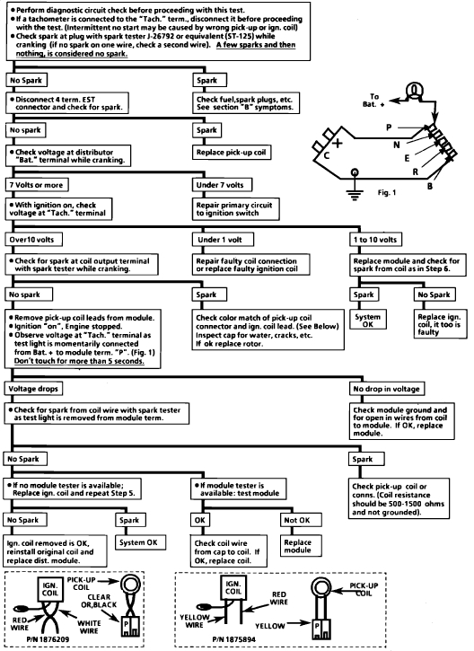
TESTING AND INSPECTION
AllData Editor Note: OE does not supply any Component testing for the Ignition Control Module. The way OE has you Test an Ignition Module is by checking for proper inputs. If all the inputs are there, and the module doesn't either fire a coil, and/or referance the Engine Control Module (to energize an injector), the Ignition Module is bad.
If the vehicle cranks for at least 5 seconds and the Engine Control Module doesn't see a referance signal, some Models will set a code, 42 (Hard) or 12 (Soft). If your vehicle has one of these codes, begin with the Diagnostic System Check in Computers and Controls, then proceed to the Trouble Code Chart (Yes, some vehicles have a DTC Chart for Code 12).
If the vehicle does not set a code, begin with the Diagnostic System Check, and it will send you to a Diagnostic Chart that checks for your particular condition.
______________________________________________________
Here are the directions for getting codes. Picture 1 correlates with these directions.
ACCESSING AND READING DIAGNOSTIC TROUBLE CODES
ALDL connector
The ECM incorporates a diagnostic program which, when activated, will flash codes stored in the trouble code memory through the ``Check Engine'' Lamp (CEL). A diagnostic connector, located under the instrument panel, is used to activate the self-diagnosis system. The connector, Fig. 6, allows access to system circuits and contains a test terminal which, when grounded with the ignition on and engine stopped, causes stored trouble codes to be flashed on the CEL.
When the test terminal is grounded with the ignition on and engine stopped, codes are displayed in numerical order, always starting with code 12 which indicates that the self-diagnosis system is operating properly. Trouble codes are displayed in the following manner: Code 12 is displayed by one flash, a short pause, then two flashes and a longer pause. Code 12 will be displayed 3 times in this manner, then any additional codes stored will be displayed 3 times each in a similar manner until all codes have been displayed. Once all codes have been displayed. The process will be repeated as long as the test terminal remains grounded.
After trouble codes have been noted, the ground wire should be removed from the test lead and the engine should be started. When the engine is started and there are no other codes except 12, the CEL should go out after approximately 5 seconds, indicating that the ECM has not detected a malfunction. However, if the ECM detects a current malfunction, the CEL will remain illuminated while the engine is running. A trouble code indicates a possible system malfunction. If a trouble code can be obtained, even if the CEL is off when the engine is running, the malfunction is intermittent and it may be necessary to road test the vehicle to observe conditions under which the malfunction occurs. Use of a SCAN tester greatly reduces the amount of time necessary to diagnose intermittent malfunctions.
Perform the ``Diagnostic Circuit Check'' referred to in ``System Testing'' to ensure the self-diagnosis system is operating properly. Follow steps as indicated in the Diagnostic Circuit Check and perform indicated corrections before proceeding with further tests.
_____________________________________________________
The second picture is a diagnosis flow chart for the ignition control module.
____________________________________________________
Let me know if this helps.
Cheers,
Joe
Images (Click to make bigger)
SPONSORED LINKS
Friday, June 8th, 2018 AT 8:33 PM